Electrical energy is often used to generate heat via various basic principles of physics.
Every engineer knows about heat, an omnipresent companion to nearly all electrical, mechanical, and chemical processes. In some cases, this heat creation is intentional and desirable; in others, the heat is unavoidably a consequence of normal operation and is detrimental.
This FAQ will look at the three ways electrical energy and power are used to create heat, using resistive, inductive, and dielectric-based principles. Each has its place and role in modern technology, systems, and processes.
Q: To re-state what is obvious, what are some of the roles of controllable heat generation?
A: Society and civilization as we know them could not exist without heat sources. Heat is needed for cooking food, chemical reactions, industrial processes, keeping warm, and more. Beginning with fire, the ability to create heat on demand has been critical. Using electricity, it’s possible to generate heat on demand and control and modulate it as needed.
Q: How much heat are we talking about?
A: The amount of heat desired, as defined by the measured temperature, can range from a few degrees above ambient to thousands of degrees. This corresponds to a few watts or kilowatts, or even megawatts.
Q: How can heat be generated?
A: There are many well-known ways, beginning with combustion using a fire fueled by wood or other fuels such as gas and oil. There is also mechanical friction, light, or sound.
Q: What about generating heat using electricity from any source as the instigator to generate heat and thus raise the temperature?
A: In general, this is an attractive way to do this, as electricity and the heat it creates can be controlled as needed.
Resistive-based heating
Q: What is resistive heating (also called resistance heating)?
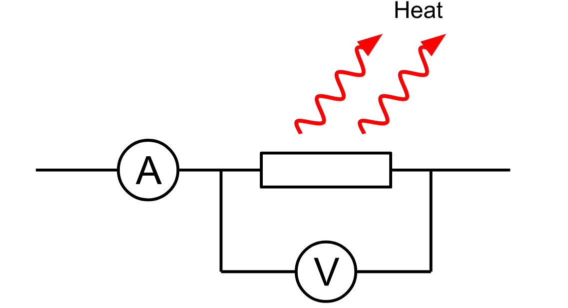
A: Any electrical current flowing through a resistance creates heat via power dissipation (Figure 1). The relationship between the current and the resultant heat as power (power is the rate at which heat energy is created or used) is simple: P= I2R (if using a current source) or V2/R (if using a voltage source).
Q: Where is resistive heating used?
A: It is used in anything from a home appliance, such as a toaster, to an industrial furnace melting steel ore.
Q: Does it matter if the applied current is AC or DC?
A: Not at all. In fact, the root-mean-square (RMS) value of an AC waveform (which does not have to be a sinusoid) is defined by the DC value, which creates the same amount of heat. Prior to the availability of RMS-to-DC converter circuits and IC, this equivalence was used in test instrumentation to measure the RMS value of a voltage. The unknown AC signal was applied to a resistance, while a controlled and known DC signal was applied to another resistor of the same value. The temperature of the two resistors was measured simultaneously. When they were equal, the RMS value of the non-DC waveform would be known.
Q: What material can be used for the resistor in resistive heating?
A: Any material that conducts electricity will work in theory. Of course, the actual material depends on the current value, the voltage, the amount of heat energy desired, and the temperature.
Q: What is the underlying material and physics principle whereby current flow through a resistance generates heat?
A: The most straightforward way of thinking about resistance is that the current-carrying electrons collide with the atoms that make up the conductor; here, “collide” means the electrons can interact with the atoms via the Coulomb force. The kinetic energy of the electrons is transformed into the vibrational energy of the atoms. Since temperature is the manifestation of vibrational energy, energy lost from resistance will heat the conductor.
There are also more detailed explanations that go deep into quantum physics. Fortunately, all you need to know are the simple equations relating current, voltage, and resistance to use resistive heating.
Q: Can you use copper as the resistance element for heating?
A: Yes and no, as it depends on the situation’s specifics. Ordinary copper wire dissipates heat due to its inherent resistance. In some cases, this creates a large enough rise in the ambient temperature to be a problem, while it is negligible in other cases.
For example, one of the engineering advances that makes modern MRI systems practical with their extremely powerful electromagnets is the development of magnets cooled to a few degrees kelvin by liquid helium. These magnets are thus superconducting with zero resistance and heat creation. Prior to this, the self-generated heat in the mange coils due to wire resistance and hundreds of amps of current would overheat the electromagnets and cause them to fail.
Q: Can you use ordinary copper wire to create heat for more modest applications such as a toaster?
A: To create the needed heat from a 120/240 VAC line, you would need hundreds of feet of copper wire, which would be costly and take up a significant amount of space. The obvious solution is to use thinner wire with a higher resistance, but such wire is structurally fragile, and the induced heat would soon melt the thin strands of wire.
Q: What’s the alternative to using copper wire for electrical-based heating?
A: A special type of wire called “resistance wire” is the answer (it is sometimes called “low-resistance wire,” which can be confusing since it has higher resistance than plain copper). The best known is nichrome wire; the most common is Nichrome 80, an alloy nominally composed of 80 percent nickel and 20 percent chromium, plus traces of iron. This mixture gives the wire great mechanical strength and resistance to oxidation at high temperatures and is rated for continuous use at up to 1200°C (~2200°F).
The resistivity of nichrome is about 65 times that of copper for a wire of the same. It is widely used for applications such as electronic cigarette and vape coils, hot-wire cutters for foam/plastics/rubber, and tools and appliances that use an enclosed heating element, such as soldering irons, hair straighteners, clothing irons, toasters, and water heaters. In short, copper wire is better for conducting electricity, while nichrome wire is better for generating heat.
Q: What about using a standard passive resistor as a heating element?
A: These resistors are unsuitable for heating, although they self-heat as current flows through them. In most cases, such self-heating is undesirable for multiple reasons: 1) it represents waste and loss of electrical power; 2) it adds to the system thermal load, with heat which may have to be removed or directed; 3) the self-heating of the resistor affects its absolute resistance value, characterized by temperature coefficient of resistance (TCR) (this TCR may be negligible or unimportant in a design, or be large and adversely affect performance; 4) self-heating also contributes to a component’s reliability degradation.
We have thus far examined resistance-based heating, the simplest form of electrically sourced heating, to understand and implement. Next, we will examine inductive heating using an electrically conductive load.
Inductive-based heating
Q: What is inductive-based heating (also called induction heating)?
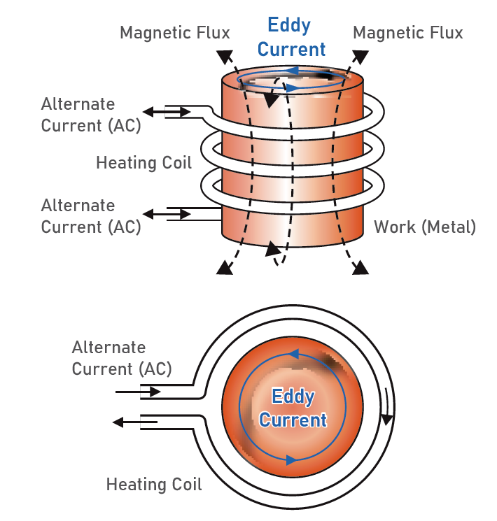
A: In induction heating, an electromagnetic (EM) field created by an RF source excites electrical currents in the material within the inductor’s EM field (Figure 2). Since the material will have resistance, these currents heat the object. The amount of heat generated depends on the magnitude of the induced currents, the material’s resistance, and the duration of the magnetic field.
Q: What are the top-level attributes of inductive heating?
A: Often called induction heating, it is a fast, efficient, precise, and repeatable non-contact method for heating metals or other ferrous (magnetic) materials. However, it cannot be used with non-ferrous metals such as copper or aluminum unless “alloyed” with a ferrous metal. Doing so may adversely affect the metal’s performance characteristics and, thus, suitability for various applications.
Inductive heating has already been examined in a five-part series in EE World, so we will not repeat that material here (see Related EE World content list at the end).
The next part of this article looks at dielectric-based heating, a more abstract concept and more complicated principle.
Related EE World content
Basics of induction heating, Part 1: Introduction
Basics of induction heating, Part 2: Principles
Basics of induction heating, Part 3: Implementation
Basics of induction heating, Part 4: Consumer use
Basics of induction heating, Part 5: Do-It-Yourself versions
Reverse-conducting IGBT targets induction heating apps
Ultra-Slim Resistive Heaters
Polymers feature tuning for low dielectric, conductive, magnetic absorption, and electrical absorption properties
Can you tell the difference between an electrolytic and supercapacitor?
The effect of DC bias on MLCC class 2 capacitors
Circuit boards don’t behave the way you think they do
How trace roughness, glass weave, and stackup affect signal integrity
Does a planet have a capacitance?
External references
Ferrite Microwave Technologies, “Dielectric Heating Explained” (has list of frequency allocations for RF heating
Physics Forums, “Resistance Differences: Nichrome vs. Copper Wire”
Remington Industries, “Nickel Chromium Resistance Wire”
Tutorials Point, “Dielectric Heating: Working Principle and Advantages”
Linn High Temp GmbH, “Dielectric heating” (long, interesting technical paper)
Brittanica, “Radio-Frequency Heating”
ResearchGate, “Is it accurate the phrase “all Dielectrics are Insulators, but not all Insulators are Dielectrics?”
Matsusada Precision Inc., “Dielectrics vs. Insulators”
Physics Stack Exchange, “What is the basic difference between insulator and dielectric?”
Microwave Journal, “Emerging Microwave Heating Applications Incorporate Solid-State Semiconductors”



Leave a Reply