Electrical energy is often used to generate heat via various basic principles of physics.
Part 1 looked at the three ways electrical energy and power are used to create heat, using resistive, inductive, and dielectric-based principles.
Dielectric-based heating
Q: What is dielectric heating?
A: Dielectric heating is non-intuitive, hard to grasp, and the contradiction of inductive heating, at least in a non-technical sense. In dielectric heating, materials with poor electrical conduction are placed in a varying RF EM field. Typically, these systems will have two metal plates that serve as electrodes, and the material between them forms a capacitor.
Q: How does this create heat?
A: The heat results from electrical losses in the dielectric material forming the capacitor. The advantage of dielectric heating is that the dielectric is uniform, resulting in uniform heating throughout the object.
Q: What’s the relationship between dielectric heating and water?
A: For materials containing water, the RF generator creates an alternating electric field between the two electrodes. The polar water molecules in the material will reorient in response to the varying polarity of the electric field, and the friction resulting from this molecular movement will result in heat.
Q: Is dielectric heating only a lab or an advanced industrial technique?
A: On the contrary, it is the basis for the standard microwave oven, developed just after World War II in 1945. The term dielectric heating represents the lower radiofrequency and microwave bands of the electromagnetic spectrum. This heating is often referred to simply as “microwave heating,” even if that is not strictly the case.
Q: What frequencies are used for RF-based heating?
A: RF heating typically uses the frequency range of 1 MHz to as high as 300 GHz, although most systems use the spectrum from around 900 MHz to 3 GHz. By international agreement, certain frequencies have been allocated for industrial use to minimize interference with telecommunications. These are 13.56 MHz, 27.12 MHz, a band within the range of 896–915 MHz, and 2450 MHz. Ironically, consumer microwave ovens use 2450 MHz, which is especially effusive with water molecules but also in one of the Wi-Fi bands (see Related EE World content for specific allocations).
Q: What are the virtues of using dielectric heating?
A: The advantages of dielectric heat for drying, cooking, thawing, and melting foods are that heat generation is rapid and occurs throughout the body of the food material. An additional advantage of drying is that water is heated more quickly than the other components of the food.
Q: How does this differ from conventional heating?
A: In conventional drying methods, heat is transferred to the surface of the food by convection, conduction, or radiation (Figure 1). It then transfers throughout the body of the food by conduction. Some penetration does occur in the case of radiant heat, but this is limited and often difficult to control.
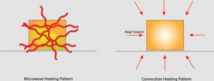
Q: How does the RF of dielectric-heating power get “into” the material or food?
A: The penetration of electromagnetic waves in the dielectric range into materials such as foods depends on the material’s frequency and characteristics. Lower frequencies with their longer wavelength have greater penetration.
Q: How is this penetration quantified, and what are typical numbers?
A: Penetration is usually quantified by half-power depth, meaning the thickness of the material, which reduces the wave energy to 50% of the incident level. The half-power depth for water is about 12 millimeters at a frequency of 2450 MHz and 75 millimeters at 100 MHz. Penetration into foods is less than into water.
Q: How does dielectric heating’s “process” compare to conventional outside-in heating?
A: In dielectric heating, heat is transferred into the body of the material rather than just to the surface. When a wet material is exposed to high-frequency electromagnetic radiation, dipolar molecules — such as water— are stressed by the alternating magnetic field, generating heat. This is the main mechanism that causes heating when MW energy is applied.
Q: Is there more to this story?
A: Of course! At the lower RF frequencies, ionic conduction plays a part. The electric fields accelerate ions present in the material, and this leads to the generation of heat. Since most foods contain ions in the aqueous phase, RF heating can be effectively applied to them.
Q: How does this differ from conventional heating using convention or conduction?
A: In dielectric heating, the relatively rapid heat generation within the material causes rapid water evaporation. This creates a total pressure gradient, which results in the rapid movement of liquid water and water vapor to the surface. Thus, shorter drying times and lower product temperatures are attainable compared to more conventional heating methods.
Heat is generated when an object is subjected to an electromagnetic field. Dielectric losses cause this. These losses result from the polarization of ionic particles in the material (millions of times per second) due to the oscillation of the electromagnetic field. This rapid polarization essentially creates molecular friction, which translates into thermal energy, increasing the temperature of the material.
Water molecules are among the most polar molecules and so are more “dielectrically lossy.” As a result, they heat the fastest and most efficiently. This is why dielectric heating (read = microwave heating) is excellent for drying applications.
Q: All this talk of “dielectric” is confusing. Is a dielectric just another term for an electrical insulator?
A: Yes and no. An electrical insulator is a material whose internal electric charges do not flow freely, which makes it very hard to conduct an electric current under the influence of an electric field.
Q: What does that actually translate to?
A: Most insulators have a large band gap. This occurs because the “valence” band containing the highest energy electrons is full, and a large energy gap separates this band from the next band above it. There is always some voltage (called the breakdown voltage) that gives electrons enough energy to be excited into this band. Once this voltage is exceeded, the material ceases to be an insulator, and the charge begins to pass through it.
In contrast, a dielectric is an electrical insulator that an applied electric field can polarize. When a dielectric is placed in an electric field, electric charges do not flow through the material as in a conductor. Instead, they only slightly shift from their average equilibrium positions, thus causing dielectric polarization. Due to this dielectric polarization, positive charges are displaced toward the field, and negative charges shift in the opposite direction. This creates an internal electric field that reduces the overall field within the dielectric itself.
Q: What does this all mean?
A: While the term “insulator” implies low electrical conduction, “dielectric” typically means materials with a high polarizability. While dielectrics and insulators both have in common in that they obstruct DC, the dielectrics allow AC to pass since a capacitor element using the dielectric will have resistance (impedance) corresponding to the frequency. This means that the dielectrics are AC conductors. On the other hand, the insulators do not conduct electricity in either DC or AC circuits.
Q: Capacitors use various dielectrics as their internal insulating material. What’s going on there?
A: Dielectric materials are also used in capacitors, but electricity does not directly pass through the dielectric. Therefore, the dielectrics are categorized as insulators. However, the dielectrics have the property of passing high-frequency AC currents with an impedance (resistance). While dielectrics are categorized into insulators, they can store electricity and provide electrical resistance in AC circuits.
The dielectric material will become polarized when sandwiched between positive and negative electrodes. Dielectric polarization occurs when an electric field is applied. An alignment of positive and negative charges occurs at the molecular level, resulting in polarization corresponding to positive and negative electricity (Figure 2).
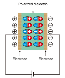
The polarized dielectrics have the property of attracting electrons onto the electrodes. The polarization prevents some of the electricity (electrons) from leaving the electrodes of the capacitor, which causes it to store electricity. In an AC circuit, as the frequency increases, the positive and negative charges on both poles of the capacitor are frequently switched, and some of the electricity that cannot leave the capacitor electrodes resists the switching, which becomes the impedance.
Q: Can you put some physics and equations around the dielectric situation?
A: Yes. The underlying physics is complicated, but analysis shows that the dielectric heating power is proportional to the applied frequency and square of the applied voltage across the dielectric: P ∝ (f × V2).
Another key parameter is loss angle δ, a dielectric material’s inherent dissipation of electromagnetic energy (heat).
Q: What is the dielectric constant?
A: It is a number without dimensions usually represented by the Greek letter kappa (κ) and is an indicator of polarizability and, thus, inductive-heating potential. The dielectric constant shows the polarizability ratio compared to a vacuum, which varies depending on the dielectric type (Table 1).
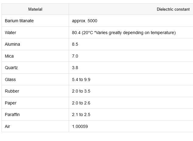
Dielectric material obviously affects both capacitor and heating performance. For capacitors, dielectric heating means that capacitors will self-heat as a function of the applied waveform type and magnitude. This self-heating affects their operating performance, can cause heat-induced deterioration, and decreases lifetime and reliability.
Conclusion
Simply put, there’s much more to electrically driven heating than well-known resistive heating. Both induction- and dielectric-based heating have roles and established usefulness, but they also have complicated underlying physics.
Related EE World content
Basics of induction heating, Part 1: Introduction
Basics of induction heating, Part 2: Principles
Basics of induction heating, Part 3: Implementation
Basics of induction heating, Part 4: Consumer use
Basics of induction heating, Part 5: Do-It-Yourself versions
Reverse-conducting IGBT targets induction heating apps
Ultra-Slim Resistive Heaters
Polymers feature tuning for low dielectric, conductive, magnetic absorption, and electrical absorption properties
Can you tell the difference between an electrolytic and supercapacitor?
The effect of DC bias on MLCC class 2 capacitors
Circuit boards don’t behave the way you think they do
How trace roughness, glass weave, and stackup affect signal integrity
Does a planet have a capacitance?
External references
Ferrite Microwave Technologies, “Dielectric Heating Explained” (has list of frequency allocations for RF heating
Physics Forums, “Resistance Differences: Nichrome vs. Copper Wire”
Remington Industries, “Nickel Chromium Resistance Wire”
Tutorials Point, “Dielectric Heating: Working Principle and Advantages”
Linn High Temp GmbH, “Dielectric heating” (long, interesting technical paper)
Brittanica, “Radio-Frequency Heating”
ResearchGate, “Is it accurate the phrase “all Dielectrics are Insulators, but not all Insulators are Dielectrics?”
Matsusada Precision Inc., “Dielectrics vs. Insulators”
Physics Stack Exchange, “What is the basic difference between insulator and dielectric?”
Microwave Journal, “Emerging Microwave Heating Applications Incorporate Solid-State Semiconductors”



The author’s in-depth explanation of dielectric heating is fascinating, and I appreciate how they broke down the complex physics behind it. I particularly found the section on the differences between dielectrics and insulators to be enlightening and informative.