Paired resistors with low-temperature drift are critical to many precision analog circuits.
Achieving high performance, precision, and consistency in an analog signal chain requires attention to subtle details. In many cases, these details include the absolute accuracy of passive components such as resistors and the more subtle effects on component characteristics due to aging, mechanical stress, and especially temperature change.
This FAQ provides some perspectives on two critical considerations: 1) the “why” of precision resistors and 2) the “how” of various ways that vendors can fabricate them, with an emphasis on what are called “matched resistors.” It is yet another example of how, beginning nearly 200 years ago, clever, insightful electricity and electronics “experimenters” devised topologies to cancel out the effects of unavoidable component imperfection and circuit shortcomings. Note: the term “matched” in this context is totally different from, and unrelated to its use with RF impedance and impedance matching.
Q: What are matched resistors?
A: In many analog circuits, the exact resistance values of multiple resistors in a paired configuration are not as important as their relative ratio. While many cases of these resistor pairs have two resistors of the same nominal value (1:1 ratio), there are also many cases where they have different values in a critical ratio such as 10:1 and must maintain this ratio for accurate and consistent circuit performance. Even when the resistors are unequal, they are still often designated as “matched” since it is the ratiometric matching that is critical.
Q: Can you give an example of where a matched pair is needed?
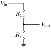
A: The simplest case is the voltage divider, which divides a larger value down to a smaller one (Figure 1). This arrangement is often used to attenuate a signal to be within the input range of an amplifier.
The output voltage is simple to determine: Vout = R2/(R1+R2) × Vin. The accuracy of the output is not a function of the absolute value of the resistors but instead is a function of their relative ratio with respect to each other. For this reason, the arrangement is called a ratiometric topology.
Note that if the two resistors have the same value, then Vout = ½ Vin. This is a clear and obvious case of where ratios matter rather than actual values.
Q: What level of ratio accuracy is needed?
A: The answer is the usual: it depends. A performance of 1% is usually the minimum needed in many cases. But — and it’s a big “but”— many precision applications need performance to 0.1% or even 0.01%.
Q: Performance to 1% seems precise enough for most designs; why is 0.1% or 0.01% needed?
A: There are two reasons:
One, the system may be intended for precision measurement, such as a lab experiment or test. Also, some measurements are very critical within a certain range. For example, if you are assessing the health and state of charge (SoC) of a nominal 3-V battery, you don’t need high accuracy when the battery is low, such as at two volts, but you may need consistency, precision, and accuracy around the full-charged value to know when to stop charging and risk overcharge damage.
Two, any errors in the reading due to resistor issues must be factored into the overall signal-chain error budget. As part of this budget analysis, it is often necessary to minimize errors wherever possible, to stay below the maximum allowable error limits. Using matched resistors may be a relatively straightforward way to give your design some more room for these other errors.
Q: Once you have picked resistors with the correct values or ratios, what should you worry about?
A: There’s a lot to worry about. First, resistors may “age” in use, usually due to the heat from their power dissipation as well as ambient heating. They may also change value slightly due to mechanical stress in how they are mounted and the imperceptible movement of the circuit board, which can induce slight changes in resistance value. If the two matched resistors incur different stress, they may shift away from their initial value by differing percentages. They may even shift in different directions, which would cause a much larger change in their ratio.
Q: What about temperature?
A: Temperature-induced changes in resistance are the largest source of potential error for matched resistors. You can buy or select resistors with matched values, but these values will change due to temperature changes, and the drift of the individual resistors will not necessarily track each other proportionally.
Q: Are restive voltage dividers the only arrangements affected by matched-resistor ratio changes?
A: Not at all. The widely used and well-known Wheatstone Bridge is another excellent ratiometric example (Figure 2).
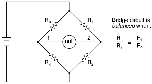
This bridge topology is used for ratiometric measurements for sensors such as strain gauges or LVDTs. Its primary virtue is that it cancels out absolute errors in resistance as long as you maintain the ratios in the “arms” of the bridge; in fact, the actual values of the resistors do not have to be known. This enables you to accurately measure an unknown resistance, such as a strain gauge, as the resistances of the unknown arms change identically.
Q: Are there other situations affected by resistor mismatch and ratio changes?
A: Of course. First, there’s the basic op-amp configured as an inverting amplifier (Figure 3).
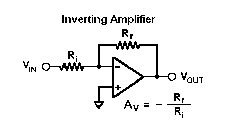
The gain is a function only of the ratio of the feedback resistor Rf to the input resistor Ri; a slightly different arrangement but with the same ratio dependency can non-inverting gain. Clearly, any changes in that ratio will affect the accuracy of the gain setting.
Q: Are these gain-related situations the only ones for which maintaining resistor-matching ratios is critical?
A: No, there are others. One important example is the impact of resistor matching on the common mode rejection ratio (CMRR).
Q: What is CMRR, and why do we care about it?
A: Consider the case where you have a small varying signal “riding” on top of a static DC signal. A common scenario for this is the last or top battery cell in a series string of cells. The challenge is to accurately measure the cell voltage Vn in the presence of the other cells (Figure 4).

If you connect any amplifier (op amp) circuit to the top battery’s positive and negative terminals in a standard differential configuration, you will see the small voltage of that battery. However, it will be offset from the ground by the large DC value of the preceding batteries. You may be looking for a few millivolts of accuracy on top of tens of volts.
Q: So, what can be done?
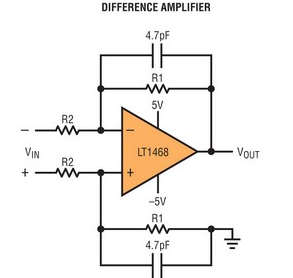
A: This larger voltage is common to both the positive and negative terminals of the battery and is called the common-mode voltage (CMV). In theory, using an amplifier in a differential arrangement will cancel out the common-mode voltage and amplify only the difference (Figure 5).
That’s the theory for an ideal op-amp. The op-amp is not ideal, and its performance is affected by the common mode voltage. The ability of the op-amp is characterized by its CMRR and is expressed in decibels (dB). Typically, an op amp’s CMRR can range from 30 dB to 80 dB and even higher.
Q: What does this have to do with resistor matching and any drifts of resistance value?
A: Without deep-diving into the equations and analysis, resistor mismatch in the differential topology degrades CMRR beyond the CMRR that the op-amp itself offers. A simplified equation for evaluating CMRR is:
CMRR (dB) = 20 log [0.5 × (1 + G/(ΔR/R)]
Where G is the nominal value of R1/R2, and ΔR/R is the resistor ratio-matching error.
Q: How does mismatch affect CMRR?
A: With 1% mismatch, CMRR will be 34 dB (not very good); with 0.1% resistors, it improves to 54 dB CMRR; and 0.01% matched resistors will result in 74 dB CMRR.
All this preceding discussion of matching, temperature-induced changes, temperature coefficient of resistance (TCR), and paired-resistance tracking is “in principle.” The next section will look at the different ways that vendors have developed to offer resistors with high precision, low TCR, and matched tracking.
EE World related content
Wheatstone bridge, Part 1: Principles and basic applications
Wheatstone bridge, Part 2: Additional considerations
Error analysis in temperature sensing with NTC and silicon-based PTC thermistors: Comparing the Ratiometric and Absolute methods
LVDT electronics, Part 1: Excitation and demodulation
Input bias current cancellation in bipolar op amps
External references
Vishay Precision Group, “Discrete Resistors vs. Networks: Making the Right Choice”
IBE Electronics, “About Matching Resistors in Electronic Circuits”
Hillman Curtis, “Resistor Matching in Analog Layout: Tips and Best Practices”
Electronic Product Design & Test,“Matched resistors maximise amplifier performance”
Analog Devices, “Precision Resistor Network”
Analog Devices, “Matched Resistor Networks for Precision Amplifier Applications”
Analog Devices, “A Deeper Look into Difference Amplifiers”
Texas Instruments, “Product Overview: Navigating Precision Resistor Networks”
Texas Instruments, “Difference Amplifiers—the need for well-matched resistors”



Leave a Reply