To get good performance from inductors in power supplies, you need to be careful about the AC characteristics. Physical inductors are complex structures, not ideal components. And the AC challenges with inductors are growing due to the higher operating frequencies of power supplies using silicon carbide (SiC) and gallium nitride (GaN) power switches. This FAQ will first look at the frequency dependence of inductors. It will then consider the various factors contributing to inductors’ losses, including DC copper loss, AC copper loss, hysteresis losses, eddy current, skin effect, and proximity effect-related losses. It closes with a brief discussion of the use of Litz wire to minimize AC losses. At higher frequencies, the AC resistance of a conductor can exceed ten times its DC resistance.
An ideal inductor passes a direct current with essentially no change. However, an inductor impedes an alternating current. The higher the frequency, the higher the impedance (Log |Z| in the image below), and the harder it is for an alternating current to flow. In an ideal inductor, the impedance rises linearly with rising frequency. Still, as indicated by the equivalent circuit, an equivalent parasitic capacitance (EPC) is present in parallel with the inductor, which causes a self-resonance.
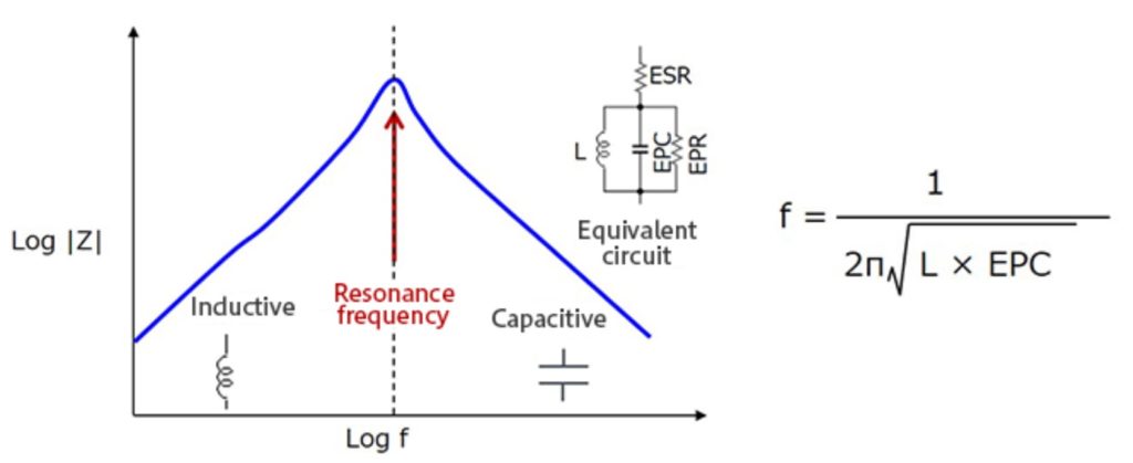
Up to the resonant frequency, the inductive characteristics dominate. Above the resonant frequency, the parasitic capacitance becomes dominant, and the device no longer functions as an inductor. As is evident in the equation above, as the inductance (L) decreases, the resonant frequency rises.
In addition to the EPC, parasitic elements of an inductor include the equivalent series resistance (ESR) of the inductor windings and the equivalent parallel resistance (EPR). These resistive elements limit the impedance at the resonance point and increase inductor losses. Many inductors are built using a core to increase inductance and minimize the size of the device. The core will have losses associated with hysteresis and eddy currents. And at higher frequencies, proximity and skin effects become significant sources of losses. The various sources of AC losses can cause inductors to dissipate energy and get hot. As a result, it is important to understand those AC losses to maximize inductor performance.

Hysteresis loss
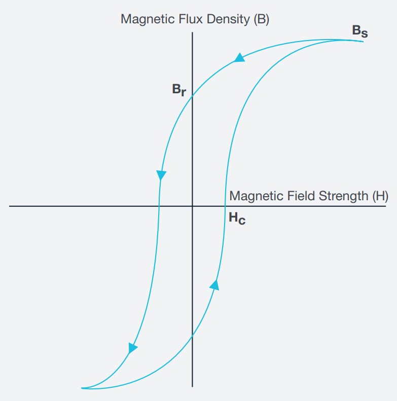
Hysteresis loss is a result of inefficiencies in the magnetization and demagnetization of the inductor core. As the current flows, it magnetizes the core, but the magnetic flux does not decrease at the same rate when the current decreases. It decreases slower. As a result, when the magnetizing force (current) reaches zero, there is still a positive flux density. A reverse current is needed to generate the demagnetizing force required for the flux density to reach zero.
The relationship between the magnetizing force, H, and the flux density, B, is shown on a hysteresis curve or loop. The hysteresis loop area shows the energy required to complete a full cycle of magnetizing and demagnetizing, and the area of the loop represents the energy lost during this process.
Eddy currents and skin effect
Eddy currents are another source of losses in inductors. They are loops of current induced by changing magnetic fields according to Faraday’s law of induction. Eddy currents flow in planes perpendicular to the magnetic field in closed loops in conductors. The magnitude of the current in a loop is inversely proportional to the resistivity of the material and proportional to the strength of the magnetic field, the area of the loop, and the rate of change of flux. Eddy current loss results in heating of the core by circulating currents induced by the magnetic field around the turns of the inductor.
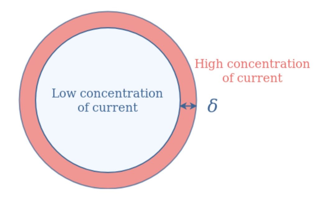
Eddy currents cause the skin effect, and the skin effect grows in importance at higher frequencies. The skin depth, δ, is the most important parameter describing the skin effect. It is a measurement of the thickness of the area where most of the eddy currents are concentrated and is proportional to 1/√f, where f is the frequency. Increasing the frequency decreases the skin depth. At high frequencies, the current is concentrated in a relatively small region, reducing the effective current carrying capacity of the wire and increasing losses. Over 98% of the current will flow within a layer 4 times the skin depth from the surface in a high-frequency design.
Eddy currents can be minimized by using magnetic core materials such as ferrites with low electrical conductivity or thin laminations of magnetic materials. Electrons cannot cross the insulating gap between the laminations. Instead, charge gathers at the lamination boundaries and produces electric fields that oppose any further charge accumulation and suppress eddy currents’ development. Structures with many laminations per unit area that are perpendicular to the applied field have a shorter distance between adjacent laminations. They are more effective in the suppression of eddy currents.
Proximity loss
The electromagnetic induction that produces eddy currents in adjacent conductors also causes the proximity effect and can greatly increase the ac resistance of an inductor. The proximity effect occurs when two or more closely spaced conductors are carrying current. The proximity effect causes current crowding resulting in non-uniform distribution of AC currents in multi-turn windings, which can lead to a significant increase of power loss compared to the power loss from the DC resistance. The proximity effect can be several orders of magnitude greater than the skin effect, and it grows exponentially with the number of layers of wire in the winding. The additional power loss caused by the proximity effect is called proximity loss.
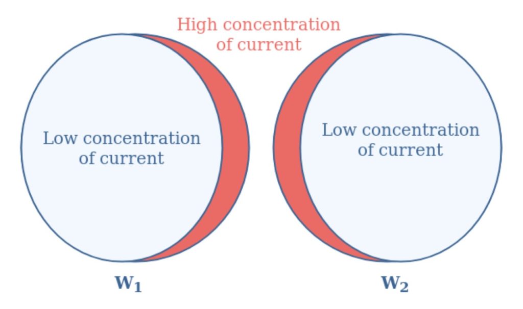
There are two forms of the proximity effect: Currents flowing in the same direction appear to “repel” each other (the direct proximity effect). Currents in the opposing directions are “attracted” together (the reverse proximity effect). Litz wire can be used to minimize the skin effect, and therefore also minimize the proximity effect.
Controlling skin and proximity effects
The term “Litz” is derived from the German “litzendraht” which means woven wire. Litz wire is fabricated with a bundle of individually insulated magnet wires. The wires are braided in a fashion that ensures that each strand takes all possible positions in the cross-section of the Litz conductor. Litz wire is used in various applications, from small ac/dc power supplies and lighting ballasts to multi-megawatt wind turbines.
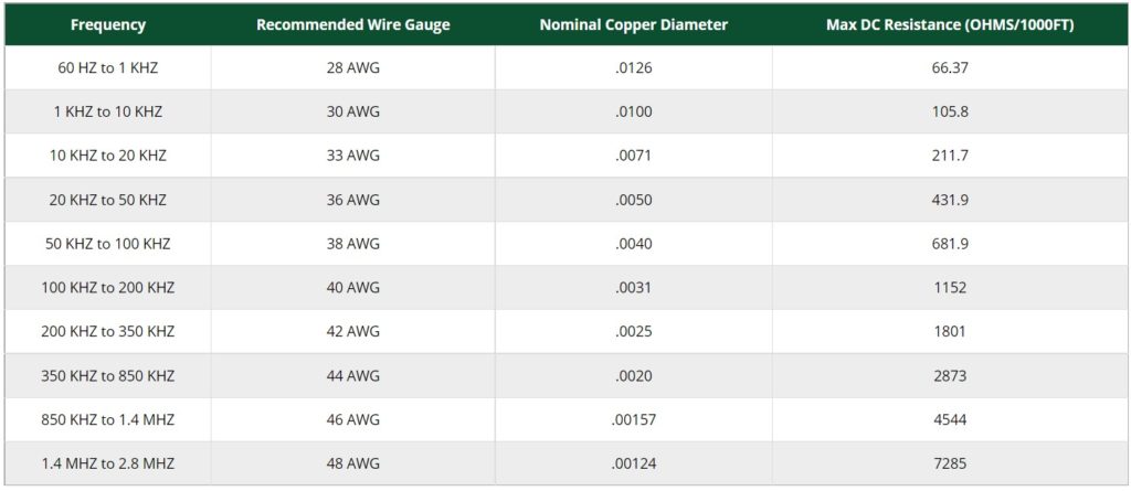
Litz wire reduces losses due to the skin effect in high-frequency windings. Litz wire is made with individually insulated strands that range from 28 to 48 AWG. Current is carried uniformly between the strands of a Litz wire, and the ratio of the AC resistance and DC resistance tends to equalize. Litz wire is engineered, so the diameter of individual strands braided into the Litz structure is close to the skin depth for the given operating frequency. As a result, current distribution is even across the entire cross-section of each wire, minimizing the impact of the skin effect and thereby minimizing AC resistance.
The operating frequency is the most important factor when specifying Litz wire. Litz wire braiding often involving several levels. Each level consists of a Litz wire branded with other similar Litz wires. The result of these winding patterns is to equalize the proportion of the overall length of each strand at the outside of the conductor. The following table shows the recommended strand gauge versus frequency for common Litz constructions.
Summary
The AC resistance of a conductor at high frequencies can exceed ten times its DC resistance. As a result, it’s very important to understand and control AC resistance in inductors. And the growing use of high-frequency power conversion based on GaN and SiC technologies is making it even more important to maximize AC efficiency. As shown, AC losses are many and complex including; AC copper loss, hysteresis losses, eddy current, skin effect, and proximity effect related losses. The use of Litz wire is one of the primary tools available to designers to minimize AC resistance.
References
Determining Inductor Power Losses, Coilcraft
Frequency-Impedance Characteristics of Inductors and Determination of Inductor’s Resonance Frequency, ROHM
How to use power inductors, TDK Corp.
In-circuit Measurements of Inductors and Transformers in Switch Mode Power Supplies, Tektronix
Litz Wire, MWS Wire Industries
One Simple and Accurate Method of Inductor AC Loss Measurement Under Dynamic Conditions, LairdProximity loss in magnetics windings, Ridley Engineering


Leave a Reply