Modular multilevel converters (MMCs) are an advanced form of a voltage source converter. They are emerging as the preferred choice in medium- and high-voltage green energy applications like high-voltage DC (HVDC) transmission systems, medium voltage motor drives including electric vehicles (EVs), wind and solar renewable energy systems, battery energy storage systems (BESS), and EV chargers where their performance advantages include scalable multilevel output voltages, low harmonic content of the output voltage and output current, modularity, flexibility, higher efficiency, lower greenhouse gas (GHG) emissions, and redundancy.
This FAQ compares the operation of MMCs with the two-level voltage source converters (2L-VSCs) they are replacing, looks at MMC reliability considerations, briefly reviews the use of MMCs in HVDC and PV systems, and closes by presenting the performance improvements possible by replacing silicon (Si) IGBTs with silicon carbide (SiC) MOSFETs.
2L-VSCs are still the most common solution, but MMCs are getting most of the attention looking to the future. 2L-VSCs generally have lower efficiency and poor power quality — especially harmonics seen by the load — compared to MMCs. Still, MMCs are much more difficult to control, slowing their adoption in many instances. A more detailed look at 2L-VSCs versus MMCs reveals several advantages for MMCs, including:
- Modularity makes them easy to expand and supports redundant operating configurations that can make systems using MMCs more fault tolerant.
- The harmonic content is not just lower; it’s more concentrated at high frequencies and the fundamental frequency, simplifying filtering.
- Many MMC designs use smaller passive filters, reducing system losses (copper and core losses in the filters) and reducing system costs.
- The dv/dt voltage stress on the power switches can be reduced by using lower-cost semiconductor devices. The lower dv/dt values also reduce electromagnetic interference (EMI) challenges and stress on the galvanic isolation components.
- Interleaving multiple levels (phases) can make it possible to reduce the fundamental switching frequency minimizing switching losses.
- Systems can be serviced by simply swapping out damaged modules, reducing operational costs, and improving availability.
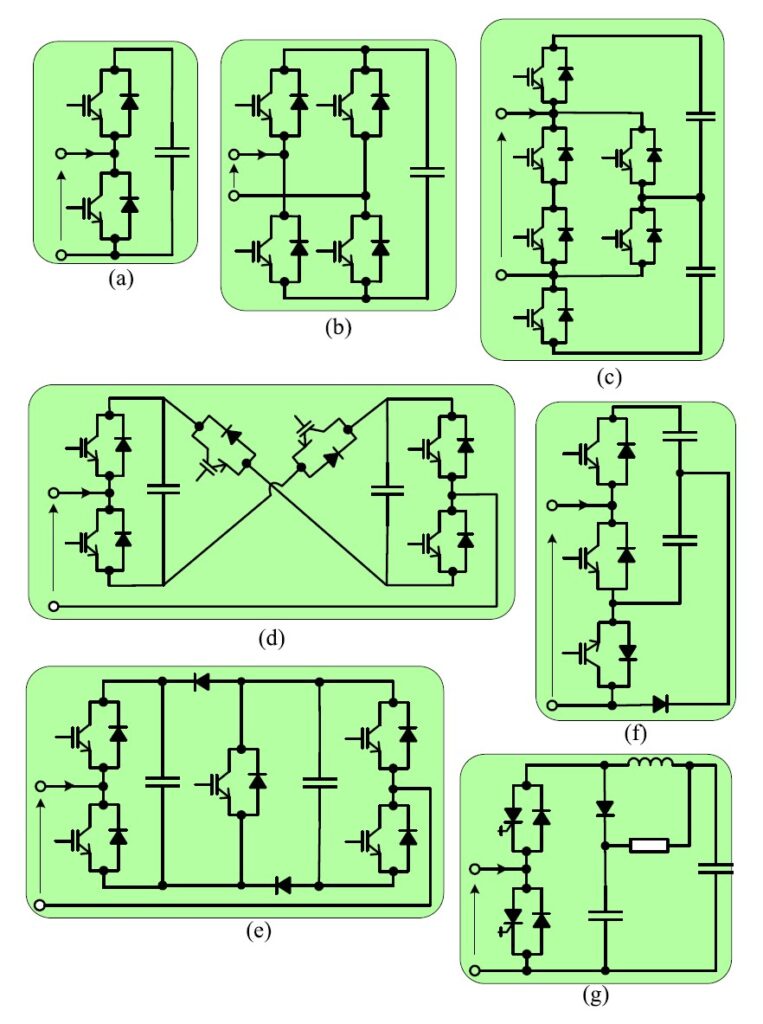
MMCs feature a series of interconnected submodules that produce a multilevel output voltage waveform for various applications like three-phase systems. The modules can support a wide range of topologies, including (Figure 1):
- Cascaded H-bridges (CHB) and half bridges are the simplest approaches and are currently the most common being developed.
- Modified active-neutral-point clamped (ANPC) uses lower loss submodules and can be appropriate when unipolar output voltages are sufficient.
- Bipolar submodules like the cross-connected submodule (CCSM) and the clamped double submodule (CDSM) have fault-blocking abilities and controllable negative voltages.
- Single-clamped submodules (SCSM) have bypass clamping diodes that support fault-clearing MMCs.
- Applications that need higher voltage ratings can use integrated (sometimes called “insulated”) gate commutated thyristor (IGCT)-based submodules that can provide higher efficiency and improved reliability.
Depending on the application, a variety of pulse width modulation (PWM) control techniques are used with MMCs. They are generally classified by the switching frequency as high switching frequency pwm (HSF-pwm), low switching frequency (LSF-pwm), and fundamental switching frequency (FSF-pwm). At higher frequencies, semiconductor switching losses increase. With today’s IGBT-based solutions, HSF-pwm is limited to applications with a small number of submodules, and LSF-pwm and FSF-pwm are used for systems with more submodules. As discussed below, a switch from IGBTs to SiC MOSFETs is expected to enable higher pwm frequencies in systems with higher numbers of submodules.
MMC reliability
High levels of reliability are often demanded in the applications that employ MMCs. There are several approaches to handling faulty submodules. Some of the most common are:
- including redundant submodules which are continually in operation (e.g., N+1 redundancy)
- including spare submodules that are only activated when a working submodule fails
- not including any additional submodules and using active submodules at higher-than-rated voltages until the failed module can be replaced
To sense when a submodule fails generally requires one voltage sensor per submodule. Alternatively, a capacitor voltage measuring system using fewer voltage sensors has been developed. This alternative approach can improve fault tolerance for voltage sensor failure and detect both open- and short-circuit semiconductor faults.
MMCs for HVDC
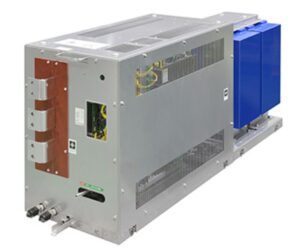
Before VSCs were implemented with MMCs, HVDC systems used line commutated converter (LCC) topologies. While LCCs have a fixed current polarity, VSCs have a fixed dc voltage polarity, making it easier to implement fast power reversals and create meshed multi-terminal HVDC grids. VSC-based HVDC systems are also smaller and better at quickly controlling active and reactive power. Those and other features have enabled the use of HVDC in applications like offshore wind farms. The submodules developed for high-efficiency HVDC power distribution are based on parallel-connected IGBTs (Figure 2).
Grid connected PV
Voltage source inverters (VSI) based on MMCs, sometimes called modular multilevel inverters (MMIs), are being developed for use in grid connected PV arrays. In these applications, using a two-level approach results in discontinuous input and output currents, requiring large filtering elements to control EMI and power factor. Plus, large transformers are needed for line frequency operation. For example, in a 2 MVA, three-phase, two-level design, the oil-filled 35.5 kV output transformer can weigh 6100 kg and have a volume of 11.3 m3. On the input side, maximum power point tracking (MPPT) is challenging since large numbers of PV modules can be subject to partial shading reducing their output and potentially causing system imbalances. Designers of MW-scale PV inverters face numerous challenges, including:
- Galvanic isolation is required between the PV array and the grid.
- IGBT ratings and losses can limit system performance.
- MPPT can be difficult to optimize as the arrays continue to grow.
- Step-up transformers and passive filters can be large and costly.
MMIs can be used to address these and other issues. Bulky power transformers can be replaced with smaller isolation transformers operating at higher frequencies instead of the grid frequency. And MMIs operating at higher frequencies have better harmonic performance reducing the size, weight, and cost of filtering elements, making it simpler to comply with utility grid regulations. Compared with conventional centralized inverter architectures, MMIs have better fault tolerance and reliability. Finally, MMIs can support modular and scalable solutions enabling PV plants to get larger or smaller as required to maximize financial returns.
WBGs for MMCs
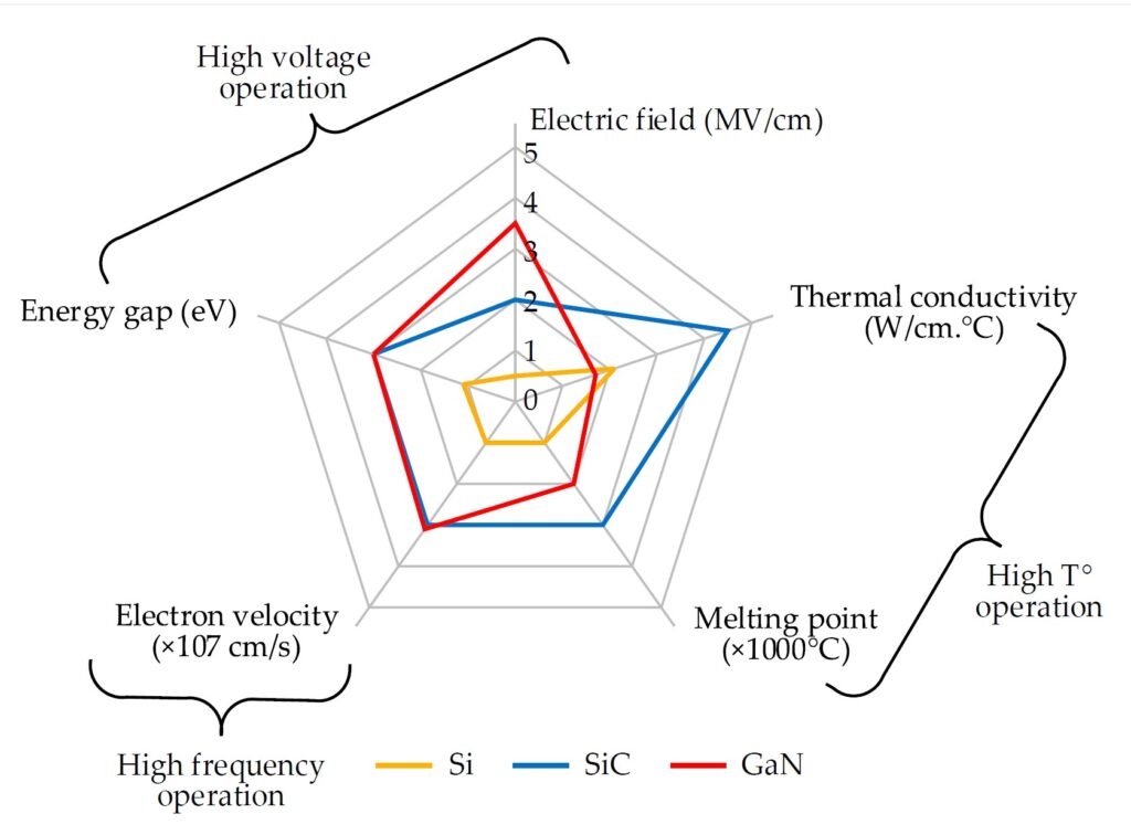
WBG semiconductors like SiC can amplify the benefits of MMCs by supporting increased energy efficiency, higher switching frequencies, higher power densities, and lower-cost cooling solutions due to better electrical and thermal conductivities. Both gallium nitride (GaN) and SiC are used in a growing range of power conversion applications. GaN is more suitable for lower-voltage applications, while SiC is suited for higher voltages. There is overlap in the mid-voltage range, but for the voltage levels required for MMCs, SiC devices are more competitive and offer the best combination of high-voltage, high temperature, and high-frequency operation (Figure 3).
SiC in MMCs
The adoption of MMCs in a range of green energy applications is already resulting in reduced greenhouse gas emissions and improved sustainability. Replacing Si IGBTs with SiC MOSFETs is expected to lead to further performance improvements.
Development efforts are well underway to use SiC MOSFETs in MMCs. One effort started with comparing HSF-pwm techniques, including phase-shifted carrier-based pulse width modulation (PSC-pwm) with triangular carriers, PSC-pwm with sawtooth carriers, and phase-disposition pulse width modulation (PD-pwm). In a conventional MMC design, PSC-pwm offers better output performance but generates higher power losses than other modulation approaches.
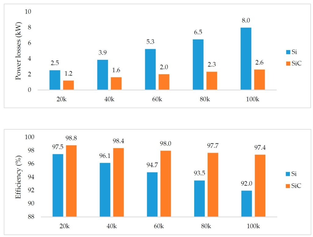
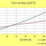
PSC-PWM modulation was used to compare Si IGBT-based and SiC MOSFET-based MMC designs using switching frequencies from 20 to 100 kHz. The study compared the semiconductor power losses and the overall MMC efficiency at various frequencies. For both device types, losses increase at higher frequencies, but the power losses in the Si devices increase more rapidly. Using SiC MOSFETs enabled the MMC to maintain efficiencies above 97% over the entire frequency range, while the efficiency of the Si IGBT-based design dropped to about 92% at 100 kHz (Figure 4). That means that losses for the SiC design were 3% compared with 8% for the Si design, resulting in much more challenging thermal management needs when using Si IGBTs in high-power MMCs.
Summary
MMCs are replacing 2L-VSCs in various green energy applications, improving the sustainability of the systems and reducing GHG emissions. The use of WBG devices like SiC MOSFETs will further improve the performance advantages of MMCs, including high-voltage and high-power operations, higher frequency operation for improvements in EMI performance, higher efficiencies resulting in significantly lower power losses, which will improve reliability, and reduce GHG emissions, module costs, and sizes.
References
A Comprehensive Review of Modular Multilevel Converters, Submodule Topologies, and Modulation Techniques, MDPI energies
A Review of Modular Multilevel Converters for Stationary Applications, MDPI applied sciences
HVDC core technology, Mitsubishi Electric
Model Predictive Control of a Modular 7-Level Converter Based on SiC-MOSFET Devices, MDIP energies
Modular Multilevel Converters for Large-Scale Grid-Connected Photovoltaic Systems, MDPI energies
Modular Multilevel Converters: Recent Achievements and Challenges, IEEE Journal of the Industrial Electronics Society
Power Loss Investigation of Si-SiC Hybrid Switches in a Modular Multilevel Converter System, Journal of Physics




Leave a Reply