The automotive power window has evolved from a basic on/off switch and motor to a sophisticated motion-control subsystem with dedicated ICs.
As with most improvements, there are both expected and unanticipated ripple effects in product objectives, associated design, and actual production. As cars became increasingly “electrified” with more motors, switches, lighting, power seats, infotainment, advanced driver assistance systems (ADAS), mandated safety features, and more, one of the logical places to start rewiring was the car door and its windows.
Fortunately, the migration to using low-speed networks such as the Controller Area Network (CAN bus) or Local Interconnect Network (LIN Bus) within the car has reduced the cable-harness difficulty. Now, 12-V power needs to go only to the regulator motor in the door, while a networked switch with thinner cabling can signal the motor controller to raise/lower/stop the window and monitor performance.
Though what started out as a basic network-friendly window-motor controller soon evolved into a smart, processor-based controller with advanced performance capabilities. The enhanced window network interface/motor controller IC needs more-sophisticated power management and regulation, and that’s where a power-management IC (PMIC) is needed. The DC power for sophisticated motor-related IC needs to be monitored and managed, and it needs a self-test to ensure that any excessive variations of power or other problems are detected promptly, and appropriate action is taken immediately before there is any damage to the motor or associated components.
ICs such as the MAX16137 from Maxim Integrated Products (now part of Analog Devices) directly address this need. This low-voltage, highly accurate supervisory circuit monitors a single system-supply voltage rail for undervoltage and overvoltage fault, specifically targeting the needs of automobile power windows and their interface/controller ICs, although it can be used for similar monitoring elsewhere in the vehicle (Figure 1).
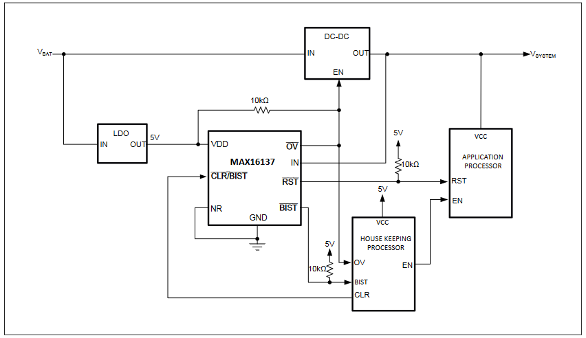
When the monitored supply voltage drops below the undervoltage threshold or goes above the overvoltage threshold, the IC’s reset output goes low; this output returns to “normal” after a reset timeout period when the supply voltage returns to within the undervoltage and overvoltage threshold window. The 1% accuracy provides supervisory consistency, while the overvoltage/undervoltage windowing value can be factory set at ±4 percent to ±11 percent of target voltage.
That’s just one role of the MAX16137. In addition, its Built-In-Self-Test (BIST) diagnostic capability monitors the health of the internal reset circuit during power-up. If that built-in self-test fails, the MAX16137 pulls its BIST output low to alert the associated processor.
As space in car doors is at a premium, the MAX16137 coming in an 8-lead, 2 × 2 mm package is an attractive fit. The advanced diagnostics at the chip level help developers meet system-level functional safety requirements with significantly reduced board-space requirements.
As the complexity of the door innards and other “peripheral” functions increases, implementing all the functions becomes an increasing problem. Managing and delivering controlled power for the various motors and mechanisms which are used for the complicated door system and adjuncts — and it is truly a system — is a substantial design challenge.
One solution is available via the STMicroelectronics L99DZ200G automotive front-door device with LIN and CAN interfaces. This IC enables a single-chip “front-drives-rear” arrangement for managing a front-door window, mirror, and lighting as well as the rear-window lift. It does this with lower quiescent current, greater reliability, faster assembly, reduced bill of materials, and shorter development time than multichip or discrete components.
The L99DZ200G incorporates two configurable half-bridges (7.5 A), two other half-bridges (0.5 A), a gate driver for an external MOSFET to control mirror heating, a control block, and a high-side driver for electro-chromic mirror dimming, and five LED high-side drivers (Figure 2).
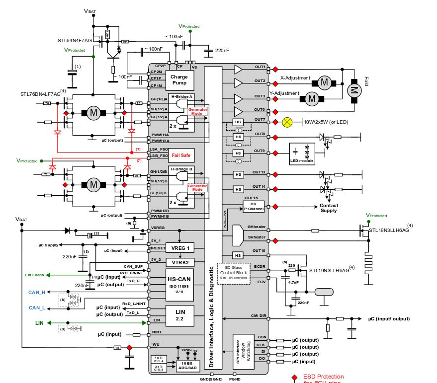
Three of the high-side drivers can operate in a constant-current mode to power lighting modules that have high input capacitance; the other two high-side drivers are suitable for controlling ordinary LEDs. The L99DZ200G also provides power management, with two 5V low-dropout regulators for the host microcontroller and peripherals. Connections for control and communication include a LIN 2.2a transceiver, high-speed CAN transceiver, and SPI 4.0 interface.
With its two bridge drivers, the L99DZ200G can control two spindle motors simultaneously and handle a third so-called “cinch motor” to close a powered tailgate or trunk. This three-motor control can be used to automatically open and close the power trunk of the car.
To do this, the two spindle motors run in parallel and in the same direction to move the trunk door up and down, while the cinching motor is activated once the movement of the trunk is completed in order to lock/unlock the trunk door. Both drivers allow operation in generator mode, which activates both low-side MOSFETs simultaneously to protect the device if an overvoltage is detected in the supply rail.
That last point is a subtlety that highlights the reality of going from conceptual design to a real production line. Carmakers traditionally protect their powered trunk drivers from manual handling at the end of the manufacturing process: when machines or workers manually lift the trunk, it automatically spins the motors and turns them into a generator that creates a voltage spike on the IC driver’s pin, which can then destroy that component.
To solve this problem, designers need to add appropriate protection components. The L99DZ200G, however, offers a new solution in the form of the generator mode, which turns on the device’s low-side external MOSFETs when the motors start to act as a generator. When that happens, the device locks the motors to prevent a voltage spike. Hence, designers no longer have to add external components to deal with this situation.
There are also reverse-battery protection and system-safety features including a configurable window watchdog and programmable reset generator. The device meets automotive standards as it tolerates 25 kV on its LIN pin and 15 kV on its CAN pin, eliminating the need for external protection components. The complexity of this IC cannot be understated: its datasheet is 198 pages long!
Conclusion
We take for granted the electronics, mechanism, and operation of the power window which is a standard feature in the modern automobile. Getting to this point, however, has been a long and challenging path requiring many design innovations. ICs address many issues and reduce the needed intra-vehicle wiring but can be complicated to set up and use.
WTWH Related Content
Understanding stop/start automobile-engine design, Part 5: Additional considerations
Understanding stop/start automobile-engine design, Part 6: Responses and work-arounds
Automobile Hands-Off Detection, Part 1: Basic issues
Automobile Hands-Off Detection, Part 2: Requirements
Automobile Hands-Off Detection, Part 3: Torque solutions
Automobile Hands-Off Detection, Part 4: Capacitive solutions
Electronic engines valves: an idea whose time has come … and gone?, Part 1: Conventional engine design
Electronic engines valves: an idea whose time has come … and gone?, Part 2: Improving the conventional design
Electronic engines valves: an idea whose time has come … and gone?, Part 3: The electronic camless approach
Electronic engines valves: an idea whose time has come…and gone?, Part 4: The camless outlook
External References
GoMechanic, “Power Windows In Cars and the Interesting History Behind Them”
Wikipedia, “Power Window”
Samarins, “Power window regulator, window motor: problems, testing, replacement”



The power windows are always the beneficial that you should know about. Thanks for the information on this topic. Subscirbed your blog.