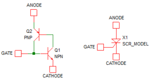
Thyristors or silicon controlled rectifiers (SCRs) and TRIACs are simple bipolar devices which probably get forgotten in this high-tech, CMOS, MOSFET, digital world. A thyristor is a PNPN bipolar device, compared to a normal bipolar transistor which will be PNP or NPN. A common way of explaining their operation is to visualize the thyristor as a PNP and NPN bipolar transistor connected together.
The gate connection is the P region shared by both devices and the N region of the PNP base is shared with the NPN collector giving the “actual” PNPN structure. Consider the two transistor version of the composite device turned off with the cathode grounded, a positive voltage on the anode and zero volts on the gate (= Q1 base) to begin with. If you then apply a small positive voltage to the gate sufficient to turn on the NPN transistor, the NPN collector current will then turn on the PNP transistor. The resulting PNP collector current will then keep the NPN transistor turned on – i.e. it is a latching device. In reality, you wouldn’t want to make a thyristor out of two transistors because you would normally want a high current device. In the two-transistor equivalent circuit shown almost all the anode/cathode current will go through the base of Q2 and it is unlikely to tolerate such a high base current.
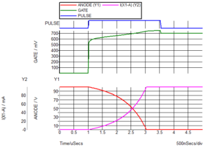
As an example, here is a simulation using the Littelfuse EC100D with 100V on the anode through a 1k resistor and a 5V gate drive through a 1k resistor. As you can see, the thyristor takes around 2µs to turn on, and when the gate drive is removed the thyristor stays turned on and will do as long as there is current flowing through the anode/cathode to maintain the latching behavior. You can speed up the turn on by increasing the gate drive current. In theory, you could turn it off by shorting the gate to the cathode but that would probably result in the maximum allowable gate current being exceeded. However, there are gate-turn-off (GTO) thyristors which are designed to be turned off with the gate, so if that is a requirement then you should look at GTO thyristors instead of ordinary ones.
The fact that a thyristor requires the anode current to drop to almost zero before it will turn off is one of the disadvantages, although it can be an advantage in some circumstances. For example, as an overvoltage clamp in protection circuitry it could stay turned on until a fuse blow or power is removed. Also, you can trigger a thyristor with a pulse from a transformer or series capacitor for example. One possible disadvantage is that they are unidirectional i.e. only for switching current in one direction – a DC switch.
The bi-directional equivalent to the thyristor is the TRIAC. There are some good diagrams of the structure on Wikipedia so I won’t repeat them here. The terminals are not anode/cathode because the TRIAC is bi-directional so they are called A1/A2 or MT1/MT2. The same principle as the thyristor is used but with some additional N and P regions connected in parallel to the thyristor P and N terminals respectively, which help fill the gaps in the thyristor operating curve. This enables the TRIAC to work in all four quadrants of operation i.e. A1/A2 polarity either way round with gate polarity also either way round.
TRIACs found significant use in phase control of AC mains for power control of lamps and other high power loads. The TRIAC would be turned on part way through the mains sinusoidal cycle. It would then turn off when the current drops to zero (at the zero crossing point of the current half cycle). The TRIAC would then be triggered again at the desired point in the next mains half cycle. As with thyristors, care must be taken when switching inductive loads.
It is worthwhile reading further if you intend to use thyristors or TRIACs because there a few potential issues that you need to be aware of such as dv/dt turn-on. If a thyristor which is turned off has a dv/dt of the anode/cathode voltage greater than a specific value then it may turn on. This means you need to be careful when switching inductive loads to ensure you include a snubber circuit to limit the dv/dt of the inductive flyback. Otherwise, the thyristor could turn back on just when you were expecting it to go off. The reason TRIACs and thyristors still exist is that they can switch high currents and voltages with small devices. They can be used as a solid state replacement for relay, for example. Thyristors are also used in simple power inverter circuits.
For an in depth reference, “Thyristor Theory and Design Considerations Handbook” HBD855/D from ON Semiconductor which is 240 pages long, covers the use of thyristors and TRIACs in some detail.


[…] to use NPN and PNP transistors and FETs What’s the difference between an IGBT and an IGCT? Not to be forgotten: the simple, bipolar SCRs and TRIACs Biasing bipolar transistor circuits Dispelling Myths: Don’t believe it when they say you need a […]