By Peter Bredemeier, Principal Engineer for Power Systems and Solutions Division, Infineon Technologies
An innovative, highly integrated combo controller for the joint control of the PFC and the hybrid flyback stage.
The Universal Serial Bus Power Delivery Specification (Revision 3.1, Version 1.1) (USB-PD) standard enables higher power levels of up to 240 W. The wide output voltage range of 5 V to 48 V, however, raises new challenges for currently used converter topologies. The combination of an AC-DC power factor correction (PFC) boost and a DC-DC hybrid flyback (HFB) stage, also known as an asymmetrical half-bridge flyback topology, can provide the right solution for USB-PD chargers and adapters with wide input and output voltage ranges. Before discussing this approach, a little background on the latest USB standard is in order.
USB-PD Extended Power Range standard
The latest IEC 62680-1-2:2022 specification defines a power delivery system that addresses all elements of a USB system. This includes hosts, devices, hubs, chargers, and cable assemblies. The USB-PD Extended Power Range (EPR) standard with 28 V, 36 V, and 48 V fixed voltages offers a universal AC-DC adapter for many different purposes, charging a whole range of end devices, from smartphones to gaming laptops, up to power tools, and even e-bikes. It defines an adjustable voltage supply (AVS) mode that allows the device being powered to request intermediate voltages between 15 V and up to the maximum available fixed voltage in these systems. Electromagnetic compatibility, power factor correction, standby power, and average efficiency requirements raise challenges for the converter topologies used up to now. Additionally, the size and, consequently, the power density becomes a more critical factor for the end users.
Design options for state-of-the-art mid-power range with wide output voltage range circuit topologies include PFC+Flyback, PFC+LLC+Buck, and PFC+Hybrid flyback topologies. Table 1 summarizes the characteristics of these approaches.
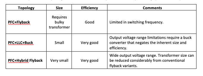
With its small size and efficiency, the PFC+Hybrid flyback topology was chosen to meet the latest USB-PD EPR V3.1 standard. This architecture also enables a high-power density with high power efficiency design to meet other international regulatory standards, such as the European Union Code of Conduct (EU CoC) Version 5 Tier 2 requirements for external power supplies, and the U.S. Department of Energy (DoE) Level VI.
Since a wide variety of devices now rely on USB Type-C for connection, communication, and power, the USB Implementers Forum (USB-IF) uses independent test labs to certify conformance to the standard before manufacturers can identify and claim conformance on specific products.
Other certifications, such as IEC62368-1:2018, “Audio/video, information, and communication technology equipment – Part 1: Safety requirements,” need to be considered as well. In this case, non-compliant products cannot be sold in major markets after the effective date.
XDP™ Digital Power Controllers
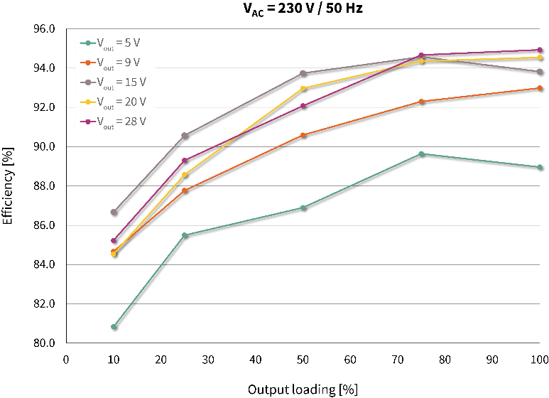
Allowing system designers to easily implement a USB-PD EPR solution, a highly integrated XDP controller XDPS2221 controls both the PFC and the hybrid flyback stages. This integration offers optimal control of both stages to deliver maximum performance. To further simplify the system designer’s task, a 140 W AC-DC reference design has been developed that achieves a full load peak efficiency of up to 95 percent and a high-power density of 22.67 W/in3 (uncased) while delivering an output voltage from 5 VDC to 28 VDC, with input voltage range from 90 VAC to 264 VAC.
Proposed architecture
To achieve the highest power density, the proposed two-stage solution consists of an AC-DC PFC boost stage and the DC-DC hybrid flyback, combined with synchronous rectification (SR) at the output. Figure 1 shows the details of the converter architecture. Gallium nitride (GaN) power devices were chosen for the switches of the PFC+HFB power stage. In addition to the three CoolGaN IGLD60R190D1 600V enhancement mode (e-mode) devices, the architecture uses OptiMOS FETs for the load switch and SR control, and the EZ-PD controller CCG3PA CYPD3175 for communication with the end device and output voltage management.
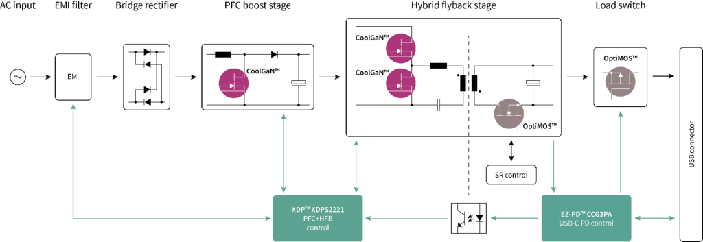
The XDPS2221 integrates an AC-DC power factor correction controller with a DC-DC hybrid flyback (HFB) controller, also known as an asymmetrical half-bridge (AHB), into a single 9.9 x 3.9-mm DSO-14 package. The integration includes a high-side driver coupled with a coreless transformer and a low-side driver driving the high- and low-side switches of the HFB stage, as well as a driver for the PFC switch. It enables a simple system structure out of the traditional flyback topology and provides the performance of a resonant half-bridge converter. Regulatory requirements can easily be met through the coordinated operation of the two stages.
Integrating all gate drivers, the GaN 600 V high voltage start-up cell for the initial IC voltage supply, and the certified active X-capacitor discharge for IEC62368-1:2018 conformance allow for a low external bill of material (BOM) and component count. Based on the zero-voltage switching (ZVS) HFB topology and GaN-based power devices, the design brings efficiency across various line/load conditions. With these features and inherent topology advantages, such as ZVS and resonant energy transfer for transformer size reduction, system designs using the XDPS2221 can achieve very high-power densities.
The combo IC controller features a synchronous PFC and HFB burst-mode operation. The converter is switched on and off during light or no load to reduce the standby power for the lowest possible no-load input standby power performance. The quasi-resonant multimode PFC stage is enhanced with automatic PFC enable/disable functionality and adaptive PFC bus voltage control to maximize average and light load efficiency. Optionally, the integrated PFC function can also be disabled to support the use case with any external PFC Controller.
The hybrid flyback stage uses peak current control operation for well-controlled regulation and fast dynamic load response. To ensure ZVS operation under all conditions, the hybrid flyback features ZVS pulse insertion, including body diode cross-conduction prevention in the discontinuous conduction mode. Additionally, the XDPS2221 provides easy-to-configure parameters via a graphical user interface (GUI) to optimize system performance.
The embedded digital core of the integrated controller allows a sophisticated control algorithm to optimize the performance of both power stages. For optimum system efficiency and reduced standby power, the PFC stage will only be enabled depending on input and output voltage conditions and load conditions. In addition, a bus voltage target modulation, depending on the operation point of the HFB, helps to increase the efficiency even further.
To reach the highest power density, it is desired to maximize the efficiency at the maximum load, typically the worst case in terms of power losses. With the newly implemented PFC modulation, it is possible to improve the efficiency for the lower output voltage levels; the modulation can enhance efficiency by nearly five percent for the lowest output voltage.
The embedded digital core supports system fine-tuning by configurable parameters. This gives designers the flexibility to adapt to different power levels and application requirements. Additionally, very high-frequency switching applications can be supported and enable the usage of a planar transformer due to zero voltage switching and zero current switching (ZCS).
Practical prototype
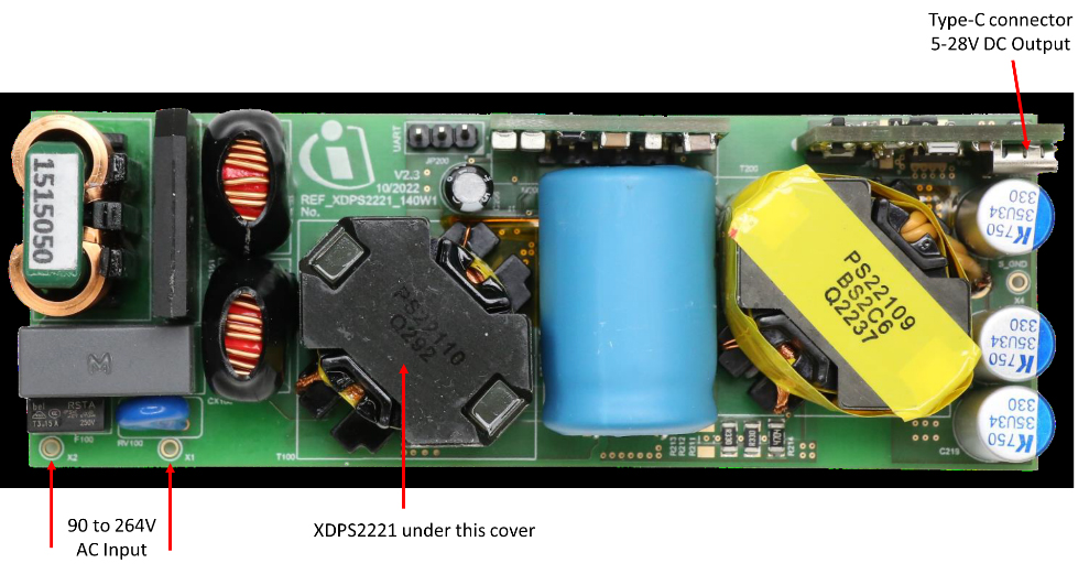
To demonstrate the described advantages, a 140 W (28 V/5 A) prototype has been developed (Figure 2). In this case, two-layer PCBs and standard magnetic cores are utilized to achieve low system cost.
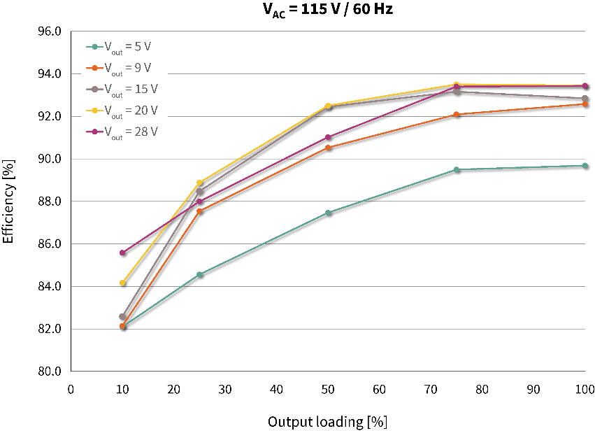
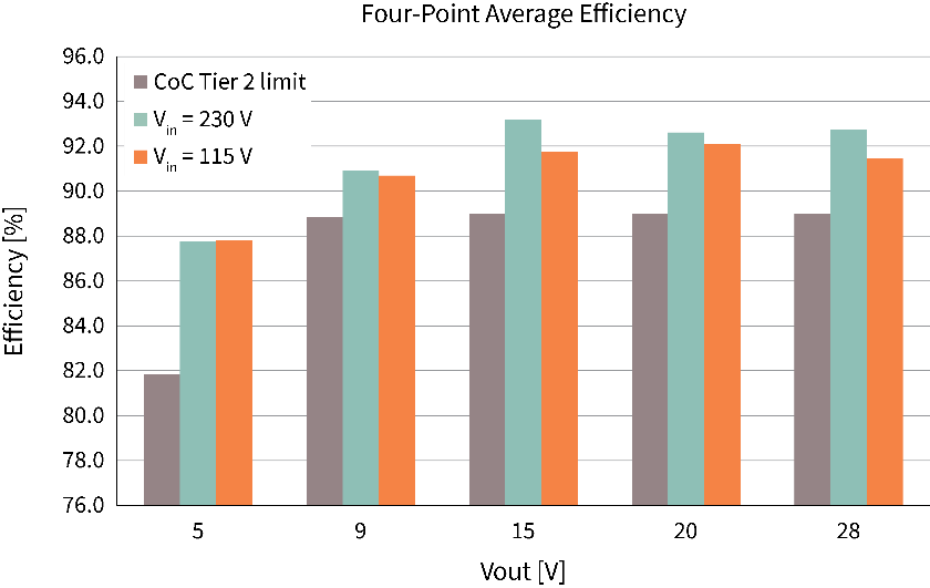
The efficiency results are shown in Figures 3 (low line) and 4 (high line). The results cover the output voltage range of 5 V – 28 V with load variation from 10 – 100 percent. The circuit reaches a peak efficiency of 95 percent at maximum load but stays above 80 percent efficiency at minimum load. This results in the following four-point average efficiency shown in Figure 5. With the integrated sophisticated control algorithm between PFC and HFB, the CoC Tier 2 limits can be easily achieved.
Due to the synchronous PFC and HFB burst mode operation, the standby losses in the input voltage that range from 90 VAC up to 264 VAC could be decreased below 70 mW over the entire input voltage range.
Efficiently and easily meeting evolving standards
The USB-PD Extended Power Range standard defines requirements for power delivery in higher power ranges for a variety of applications that use the USB Type-C connector. Combining the HFB and the PFC-boost with the control strategy demonstrates the potential for USB-PD EPR adapters to reach high efficiencies from light load to maximum load. The highly integrated controller with combined PFC and HFB operation enables a simple design in a small size to achieve a high-power density. The benefits of the proposed solution have been demonstrated with a 140 W USB-PD EPR prototype achieving high peak efficiency of 95 percent and a power density of 22.67 W/inch3 with a low-cost two-layer PCB.



Leave a Reply