The servo motor is an older precise-positioning motor arrangement now facing some competition from the stepper motor.
When engineers need precise positioning of a motor’s shaft (rotor) angle and associated mechanical system, their first thought in many cases may be to use a stepper motor (aka “stepper”). That makes sense, as stepper motors have the attributes needed for both continuous rotation and angular positioning and holding.
However, there’s another, much older motor arrangement that is also well suited to precision positioning: the servo motor and servomechanism. This system predates steppers by many decades, having been developed in the analog electronics world and even some pre-electricity all-mechanical appearances. Despite its age and the availability of steppers, the servo motor is still widely used and the best choice in many precise-positioning applications.
This FAQ will explore the operation of the servo motor and system applications, offer a brief look at its history, and compare the attributes of the servo motor with the stepper motor. It will also look at some servo amplifiers and an IC used for that function. (Note that all terms beginning with “servo” are sometimes spelled as one word and sometimes as two words, and the word “servo” is sometimes used as a standalone.)
Q: What is a servo motor?
A: A servo motor is a motor that is operated in a closed-loop, negative-feedback arrangement and is primarily used for precise positioning rather than ongoing, longer-term rotation. It uses a position sensor on the shaft to feed information about the rotor’s actual angular position to its power driver so the driver can produce a drive signal that minimizes the error between the desired position (setpoint) and the actual position (Figure 1). In this way, the motor system can accommodate changes in load, operating circumstances, and other factors while maintaining rotation and position accuracy.
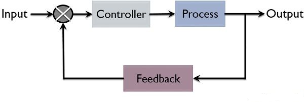
Of course, this basic block diagram significantly simplifies many details that are critical to the effective implementation of closed-loop control (Figure 2).

Q: What is the source of the position feedback information?
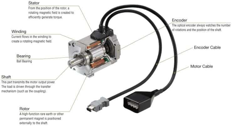
A: An encoder serves as a sensor providing speed and position feedback. This encoder can be an optical disk, a magnetic sensor, a resolver (a kind of transformer with output phase related to angle), a capacitive sensor, or a Hall-effect device; there are even some advanced wireless types. The encoder and associated circuitry are generally built inside the motor housing, so the motor and encoder are one integrated unit; hence the term “servo motor” rather than just “motor.”
Q: What are some of the applications of servo motors?
A: They are widely used in small and large applications. Many industrial and commercial systems use them for robotics, CNC (computer numerically controlled) machine-shop tools, camera lens positioning for autofocus, positioning systems that dynamically track and set positioning of the azimuth and elevation axes of antennas and optical/ radio telescopes, and gun-control turrets on naval ships.
Q: Does the servo motor use a “special” motor?
A: Yes and no. The motor itself can be one of the many of the standard motor types. What makes a servo motor special is the closed-loop feedback which enables precise positioning. The servo motor uses a regular motor (with some special “twists”) and couples it with a sensor for positional feedback. For example, the motor can be a synchronous or asynchronous AC motor or a brushed or brushless DC motor.
Q: Is a servo motor just a motor and encoder?
A: No, in many cases the servo motor unit also contains a gear assembly to reduce speed and increase torque and precision. The motor may also have a mechanical arrangement, such as a rack and pinion, to translate rotary motion to linear motion since the servo motor is often used in linear-positioning applications. There is also the position-feedback encoder in the same housing (Figure 3).
Q: Are there any other unusual aspects of the motor?
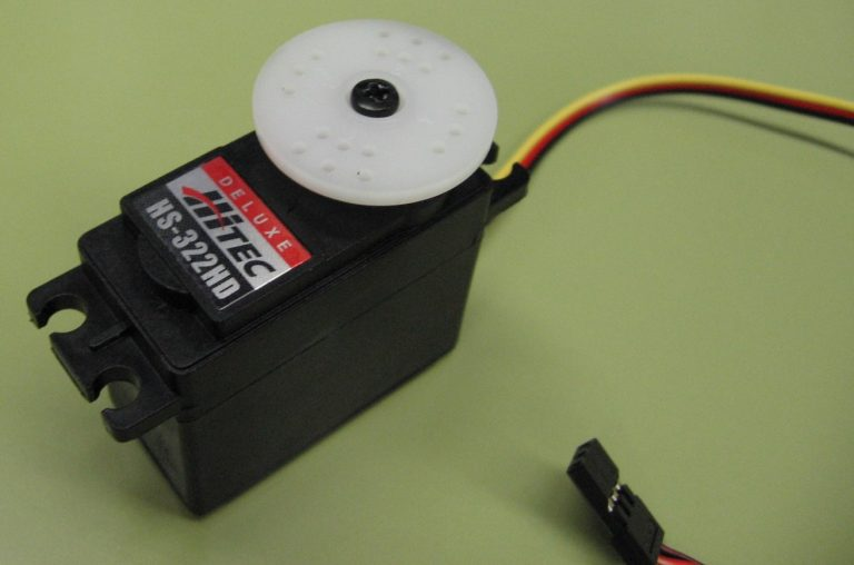
A: Regardless of motor type, the servo motor is generally designed to provide higher torque rather than higher speed. Some servo motors are designed to rotate from just a partial to full turn (180° to 360°), such as those used to control the flaps and rudders in model aircraft, boats, and drones (Figure 4); others can rotate continuously like a conventional motor.
Q: What parameters characterize the servo motor?
A: There are many important factors, but the basic ones are as expected: torque, accuracy, speed, power, and operating range.
The controller
The controller is an important part of the servo motor and is designed for this purpose. It compares the feedback from the shaft sensor to the desired setpoint value and creates a signal to drive the motor to counteract this error. The amplifier is often called an “error amplifier,” but that is somewhat of a misnomer in some ways, as it does not amplify the error but seeks to minimize it; on the other hand, it “amplifies” the (hopefully) tiny error so it is large enough to actually move the motor.
The amplifier compares the signal generated from the current position of the motor generated by the rotational-position encoder as feedback to the desired position of the motor. The amplifier error signal then drives the motor to reduce the error.
Q: What is the nature of the error-initiated drive signal to the motor?
A: It depends on the specifics of the system and the motor. It can be an increase, decrease, or polarity reversal of an analog voltage or current; it can be a change in frequency; more commonly, it is now a PWM signal with a change in pulse width, repetition rate, or duty cycle.
Q: Seems pretty simple, but is it?
A: As the error increases, the “intensity” of the correction signal to the motor also increases, and the motor rotates until the error becomes close to zero. If this correction signal is not properly managed, the rotor will likely “overshoot” and the correction signal will reverse. It may even chatter around the intended position before settling.
In short, the closed-loop operation is a classic PID (proportional-integral-derivative) action where the goal is to minimize final error, maximum rate of zeroing the path to zero error, and minimize overshoot past the zero-error point. This requires tuning the PID coefficients control loop to match the motor, linkage, and load characteristics in the context of acceptable behavior and tradeoffs.
Q: What’s the difference between a servo driver and a servo controller?
A: The servo driver (also called a servo amplifier) provides power to the servo motor. The servo amplifier takes low voltage commands for torque, speed, or position, then amplifies them into a high-powered format that the servo motor can use.
The servo controller, on the other hand, is responsible for sending commands that dictate how and when the servo motor will move. It provides specific commands to the amplifier through analog signals or data, such as “Move 10 feet at a rate of 20 feet per minute.” The servo amplifier takes that signal and provides the necessary power and signal format for the time required to accomplish that task. It does this while constantly monitoring the feedback from the Encoder. It has enough onboard control circuitry to interpret control and feedback signals.
Simply put, the servo controller feeds information to the servo amplifier through signals. The amplifier uses this information to influence what the motor does, how it does it, and when it happens. The key difference between the servo motor and the servo drive or amplifier is their distinct functions.
Q: How has the driver situation changed in recent decades?
A: Early servo amplifiers didn’t do much more than amplify the error to create electrical command signals. This was all done locally, right at the motor; you might call it a prescient case of “edge” processing. It wasn’t until later, with the proliferation of basic digital capabilities, that advanced features such as mode switching, multiple feedback options, isolation, and other features became available.
When advanced digital servo amplifiers were introduced in the 1990s, even more features, such as network communication, digital input/output, and pre-programmed moves, became possible. With more capabilities, some started to refer to servo amplifiers as servo drives instead.
Part 2 of this article goes deeper into servosystems and their constituent elements and provides a brief history of these systems.
EE World related content
What is Proportional (PID) Control and why is it used? (Part 1)
Basics of motion-control profiles, Part 1: Context
Basics of motion-control profiles, Part 2: Ramp profiles
Basics of motion-control profiles, Part 3: Implementations
Motor field-oriented control, Part 1: Principles
Motor field-oriented control, Part 2: Implementation
Motor fundamentals and DC motors
Driving brushed and brushless DC motors
The basics of AC motors and their applications
Difference between synchronous and asynchronous (induction) motors
How many electric motors are in a car?
What you need to know about MCUs for servo control
External References
RealPars B.V., “What is a Servo Motor and How it Works?”
ISL Products International Ltd., “Servo Motor Fundamentals”
Kollmorgan, “What is a Closed-Loop System?”
Association for Advancing Automation, “Servo Motors vs. Stepper Motors in Motion Control: How to Choose the Right One for Your Application”
Wevolver, “Stepper vs Servo Motors: A Comprehensive Comparison for Your Next Project”
Control Automation, “Servo Motor vs Stepper Motor: Understanding the Differences”
Machine Design, “Stepper and Servo Motor Tradeoffs”
ElProCus, “Different Types of Servo Motors: DC Servo Motor and AC Servo Motor”
Advanced Motion Controls, “Is it Servo Drive or Servo Amplifier? and Other Motion Control Questions”
Advanced Motion Controls, “Why Choose a Servo Drive vs a VFD?”
Advanced Motion Controls, “Stepper vs Servo”
ACS Industrial Services, Inc., “How to tell the Difference Between A Servo Controller and A Servo Drive or Amplifier”
Robots.com, “A Little about Servo Amplifiers”
Engineer’s garage/EE World Online, “Servo Motor Control Using 555 Timer IC”
Trinamic/Analog Devices. “TMC4671 Datasheet”
John Hannavy, “The Governor – controlling the power of steam machines”
Radwell International, “The Evolution of the Servo Motor”
IEEE Industry Applications Magazine (Volume: 2, Issue: 2, March-April 1996), “Origins of the Servo-Motor”
Rexroth Products, “Why Do We Call It a Servomotor?”
Semantic Scholar/IEEE, “Origins of the Servo-Motor”



Leave a Reply