by Stan Trout, Owner/Metallurgist, Spontaneous Materials
It can be tricky to correctly specify magnetic materials for power circuits and actuators. An understanding of definitions and common properties serves as a good starting point.
Though magnetic materials are widely used in power components, engineers frequently have misunderstandings about their magnetic properties. For example, the energy product (BH)max is the most frequently used permanent magnet property, but probably the least understood. And most engineers do not learn much about permanent magnets in school. Likely they will learn a few bits of jargon, like units and parameters, but will never really master the subtle points. So it can be overwhelming the first time an engineer becomes involved in a project involving a permanent magnet.
People designing with magnets frequently get surprised by several subtle points. These include magnet temperature characteristics, testing and the interactive nature of magnetic design; any single change has consequences elsewhere. It usually takes most engineers several tries before they feel comfortable designing with magnets. And it is quite common for designers to start the process by looking back at the last design for guidance, rather than starting from scratch.
Some magnetic materials are more difficult to design with than others. Alnico magnets, for example, are an odd material compared to ferrite, samarium-cobalt or neodymium-iron-boron. Because alnico has a relatively low intrinsic coercive field, alnico magnets must be relatively longer to prevent demagnetization. This leads to a geometry that looks long and skinny rather than the traditional short and fat. It also explains why there are few new designs in alnico.
Additionally, it is tough to develop a feel for relative magnetic strength. Mathematics only goes so far in describing magnetic behavior. As a demonstration, I’ve put ferrite, SmCo and NdFeB of the same size on a steel plate. You can feel the difference in the force as you pull the magnets off the plate. Because the magnets are the same size, it is clear to the observer that the difference they are feeling must be due to the materials itself. This demonstration works well in-person. It is much tougher to visualize these differences rather than experience them.
The bottom line is that magnetic design can be a complicated subject. But a firm grasp of the basics can help engineers get started on the right track.
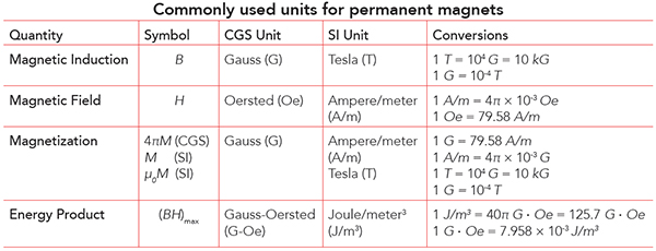
Three vectors
Most magnetic behavior is characterized in terms of three interrelated vector quantities that either describe what is happening inside the permanent magnet or in the region around it. These quantities are:
B, Magnetic induction or flux density. A vector quantity describing the concentration of magnetic flux at a point in space. It is expressed in terms of flux lines per unit of cross-sectional area. This quantity is reported as Gauss in CGS units (centimeter-gram-second) and as Tesla in SI units (Système International d’Unités).
H, Magnetic field. A vector describing the intensity of the magnetic field created by a field source, such as current moving through a wire or a permanent magnet. Correct units for reporting this quantity are Oersted in CGS and Ampere-turn/meter (A/m) in SI.
M, Magnetization. A quantity describing the magnetic state of the material, representing the vector sum of individual atomic magnetic moments per unit volume. The magnetic moments arise from unpaired spinning electrons, typically located in the 3d or 4f electron shell of each atom. The CGS unit for M is Gauss and the SI unit for M is A/m.
These three vectors are not independent, they are related. Fundamentally, induction is a combination of magnetization and magnetic field, but the exact relationship is slightly different between the two systems of units. The defining equations are
B = H + 4πM (CGS) (1a)
or
B = µ0 (H + M) (SI) (1b)
In CGS units the B and 4πM quantities are given units of Gauss, and H is in Oersteds. But equation (1a) makes it clear that Gauss and Oersteds are dimensionally equivalent. It is not unusual to hear someone refer to the intensity of a magnetic field in Gauss, although strictly speaking, it is not correct. The constant µ0 = 4π x 10–7 Tesla-m/A is called the permeability of free space. It is used only in SI units to relate H and M to B. Occasionally, µ0M = J is reported as a polarization in SI units of Tesla.
Magnetic materials display hysteresis. Hard magnetic materials (for example, permanent magnets) show a large amount of it, and soft magnetic materials show little hysteresis. A word of Greek derivation, hysteresis describes the observation that magnetic materials are highly nonlinear, meaning their response to a stimulus lags behind the applied stimulus in a consistent and repeatable manner, a hysteresis loop. The stimulus in this case is an applied magnetic field and the material’s response is the magnetization or induction.
In typical graphs of hysteresis loops, the X-axis shows the applied magnetic field, H, and the Y-axis shows the magnet’s internal response, the magnetization, M. Starting from the origin, magnetization rises with increasing field until it hits a maximum, defined as the saturation magnetization, MS. The minimum applied magnetic field necessary for saturation is called HS; it is an important practical parameter, although frequently ignored and difficult to define precisely.
As the field drops to zero, we find much of the magnetization remains, defined as Br, the remanent magnetization. As the applied magnetic field becomes negative, a significant field is necessary to reduce the magnetization to zero, defined as Hci, the intrinsic coercive field. Applying a larger negative field will saturate the sample in the opposite direction, and a symmetric pattern can be seen in the rest of the curve that finally closes back on itself again in the first quadrant.
The loop in plots of hysteresis is called a major hysteresis loop because sufficient magnetic field is applied to saturate the sample in both directions, making the enclosed area as large as possible for the sample in question. Applying a larger maximum field will not affect the enclosed area of the loop, nor does it yield any additional information about the sample. Any data supplied about magnetic materials should be based on a major hysteresis loop, unless clearly stated otherwise.

The major hysteresis loop for magnetic material typically takes on a rectangular shape when plotted with the magnetic field on the X axis and magnetization on Y. Application of a sufficiently large magnetic field saturates the sample in both directions, making the enclosed area as large as possible for the sample in question.
Applying a smaller maximum field, one that does not fully saturate the sample, yields a minor hysteresis loop. Typically, minor loops should be avoided for permanent magnets, as the size and features of a minor loop depend heavily on the maximum field supplied and not solely on the magnetic properties of the sample.
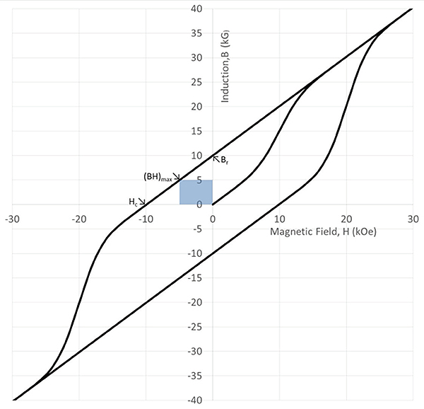
Hysteresis loops can be plotted with magnetic field on the X axis and flux density on the Y axis. Instead of flattening out at high fields, this curve assumes a fixed and constant positive slope.
Hysteresis loops can alternatively be drawn with flux density, B, which is the externally available magnetic flux, plotted against the applied magnetic field. Instead of flattening out at high fields, this curve assumes a fixed and constant positive slope. The remanent magnetization, Br happens at the same place, but the field to reduce the flux density to zero, Hc, is less than Hci. The B versus H curve also gives the energy product, (BH)max, which is the largest product of B × H in the second quadrant. (This entity represents the area of the rectangles traced out in B-H major hysteresis loops and demagnetization curves.)
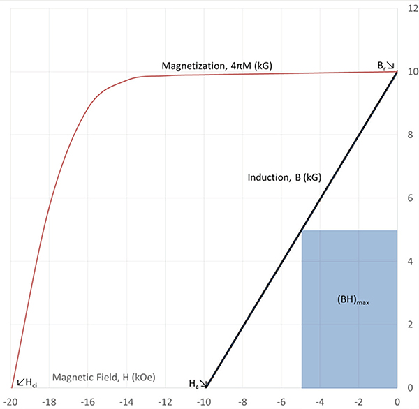
Demagnetization curves are constructed by showing the second quadrant of magnetic field versus magnetization and versus flux density plots. This eliminates information that is redundant in the complete hysteresis loops.
There is substantial redundancy in showing the complete hysteresis loop. The main interest is when the applied magnetic field is in the opposite direction of the magnetization or induction. So the standard convention in the permanent magnet industry is to show just the second quadrant of both curves together. The resulting graphs are called demagnetization curves.
Assuming ideal behavior—meaning no drop in magnetization once a sample is saturated—all the following equations are true as equalities. When real cases are considered, the greater than (>) applies.
4πMs π Br (CGS) (2a)
µ0Ms ≥ Br (SI) (2b)
Br ≥ Hc (CGS) (3a)
Br ≥ µ0Hc (SI) (3b)
Hci ≥ Hc (CGS and SI) (4)
(Br/2)2 ≥ (BH)max (CGS) (5a)
(Br/2)2 ≥ µ0(BH)max (SI) (5b)
Temperature and magnets
Permanent magnets are sensitive to temperature in several ways. We will consider three.
The first thermal quality to consider is the Curie temperature. Like nickel, most permanent magnets have a large saturation magnetization at low temperature. The magnetization begins to fall rapidly at higher temperatures, finally reaching zero at the Curie temperature Tc. Therefore, Tc is always worthy of note, but there are other thermal considerations that should be considered as well.
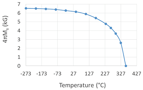
The temperature qualities of nickel mimic those of most permanent magnets which all have a large saturation magnetization at low temperature. The magnetization falls according to the pattern visible here, finally reaching zero at the Curie temperature Tc.<
Because of the behavior of magnetization over temperature, there are small and reversible changes in the magnetic parameters around room temperature. These variations are quantified in two temperature coefficients, α and β, which report the behavior of Br and Hci, respectively, the second thermal qualities to consider. The defining equations for these two parameters are:
To design a magnet application correctly, a temperature range should be given along with the reported values of α and β, for instance, 20 to 150° C. These are also called reversible temperature coefficients because these effects are completely reversed when the magnets are returned to room temperature.
The third and most conceptually difficult thermal quality is called irreversible loss, which arises when a magnet sees elevated temperatures for an extended period of time. In other words, one might see a flux loss of a few percent when a disc-shaped magnet with L/D = 0.5 is held at 150° C for a few hours. Unlike reversible loss, this loss is not reversed by returning the sample to room temperature. However, all the magnetic flux can be recovered by remagnetizing the part. In practice, remagnetization may not always be practical, so the losses are irreversible in this context.
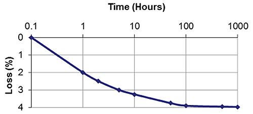
A typical curve for irreversible loss shows how flux loss rises the longer a magnet sees high temperatures. Here the soak temperature was 150° C. The time scale in these plots is typically logarithmic.
Note that the time scale in a typical irreversible loss plot is logarithmic. The exact loss observed depends on the time, temperature and shape of the sample. Usually, the losses flatten out over time, so this is a stable situation. Irreversible loss is commonly observed in rare earth magnets and should be considered in the design process.
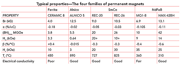
Families of permanent magnets
There are four major permanent magnet materials. Each material has at least one compelling reason to maintain its commercial interest.
Ferrite magnets cost the least in terms of dollars-per-kilogram of material, but they have the weakest magnetic properties, and Hci drops as the temperature decreases.
Alnico magnets have the lowest temperature coefficient of Br and the highest maximum operating temperature, but they have the lowest Hci. This latter property makes them easy to magnetize, but also prone to demagnetization.
Samarium-cobalt magnets, both the SmCo5 and the Sm2Tm17 (where Tm is a combination of transition metals: typically Co, Fe, Cu and Zr or Hf) compositions, have exceptionally high Hci values and a relatively low temperature coefficient of Br, but the combined high cost of both samarium and cobalt makes these the most expensive magnets in use today.
Neodymium-iron-boron magnets come in bonded and sintered forms. Sintered neodymium magnets offer the highest (BH)max, while bonded magnets offer more design flexibility. Corrosion resistance and maximum operating temperature have been long- standing objections, but generally overcome with appropriate coatings and an understanding of the thermal properties of NdFeB, when designing a new device.
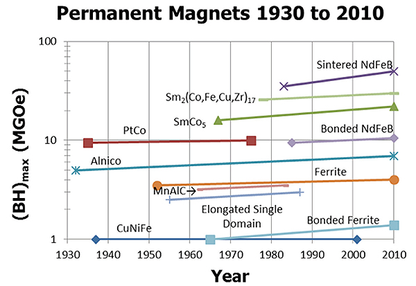
All in all, an understanding of the basics of magnetic materials begins with understanding their hysteresis loops and the basic permanent magnet parameters, for example, Br, Hci and (BH)max. Each type of permanent magnet material offers one or more reasons to consider it for use. The obligation of design engineers is to understand these reasons and the application under consideration to make good material selections.
References
Spontaneous Materials
www.spontaneousmaterials.com
The International System of Units (SI) NIST Special Publication 330 (2008) Barry N. Taylor and Ambler Thompson, Editors.
R. B. Goldfarb and F. R. Fickett, U.S. Department of Commerce, National Bureau of Standards, Boulder, CO, March 1985, NBS Special Publication 696.
Rainer Hilzinger and Werner Rodewald, Magnetics Materials, Vacuumschmelze 2013 pp. 134-135, Publicis Publishing, ISBN 978-3-89578-352-4.


Leave a Reply