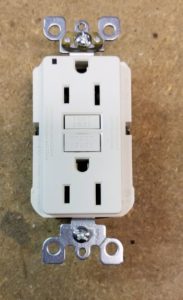
GFCIs detect hazardous current paths to ground and ground-to-neutral faults. A teardown reveals they are relatively simple but have circuit details that can be tricky to figure out.
Bathrooms, kitchens, and other rooms with access to water are required to employ ac outlets with ground-fault circuit protection. GFCIs disconnect the output if they sense a hazardous current flow.

 The GFCI function generally is controlled by a single IC. The mechanical make-up of most GFCI brands is quite similar. The usual approach is to put the electrical connections to hot and ground wires through a set of electromechanical switch contacts. The contacts feed ac to the outlet in normal operation. When the GFCI detects a problem, it powers a solenoid which disconnects the contacts. Pushing a manual reset button reestablishes the connection to the outlet.
Deconstruction teardown
A majority of GFCI outlets are held together with four screws through the back plastic housing. Removing them allows the front plastic face of the device to lift off, revealing the metal contact assembly and attachment backbone.


The plastic reset switch lifts off to reveal a spring behind it and the mechanism that pushes the electromechanical switches back into position after an actuation.
The metal frame containing the attachment points and the third-wire ground connections then lifts off the plastic housing. The connection points for the hot and neutral plug connections lift out as well. Then the front half of the plastic housing can be lifted off to reveal a view of the electromechanical contacts and the attachment points for the incoming hot and neutral wires. The electrical components sit on a single circuit board that just lifts out of the plastic housing.
A circuit board forms the mechanical backbone for the rest of the GFCI components, including the sensing toroids, wire connection points, electromechanical relay, and circuit components. It is a single-sided board with one main chip and several discrete components. The chip on this particular GFCI is a ground-fault interrupter control device from Fairchild Semiconductor (recently bought by ON Semiconductor). The other main device on the board is a silicon-controlled rectifier (SCR) from NXP used to trigger the solenoid to disengage electrical contacts in the event of a fault.
The explanation of how the GFCI operates is basically a description of the Fairchild chip functions. The chip contains a precision op amp whose inputs connect to a wound toroid. Hot and neutral lines pass through the center of the toroid.

The operative principle is that the current through the hot and neutral lines should be identical. If they are, there is no net magnetic field generated, and there should be no current induced in the toroid windings. But if the two currents are not the same, there’s a problem. The assumption is that some of the current could be flowing through a human operator.
 The current generated in the toroid windings goes to the precision op amp which converts it to a voltage. Two comparators on the chip are connected to the sense amp output. They are configured as a window detector. When the current from the sense toroid exceeds a preset level, the window detector output starts a delay circuit. If the sense current exceeds the trip current for a time longer than the preset delay interval, the chip triggers the SCR. The SCR is connected to the solenoid which actuates the electromechanical contacts, disconnecting the outlets from the line and neutral wires.
 There is a second toroid used as a current sensor in the GFCI. Judging by comments we’ve seen on forums, there is some confusion about its purpose and how it works.
The point of the second toroid is to sense current flowing from ground to neutral, rather than a difference in the line and neutral current. One point of confusion among some online commenters is how current can flow in the ground lead without causing a difference in the hot/neutral current that the first toroid would sense. The answer: One can envision a scenario in which current flows from hot to load, then to neutral, and then to ground. There would potentially be no difference in the line and neutral current. So the GFCI circuit must sense this fault current with the operating assumption that the hot and neutral currents are the same.
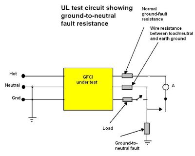
 GFCI makers can use several methods to detect ground to neutral current. The Fairchild chip uses a scheme which makes use of the definition of fault current resistance as spelled out in UL 943, the U.S. standard for ground-fault circuit interrupters. The standard specifies that GFCIs trip with fault currents of 6 mA for specified ground fault resistances and for a specified combination of ground to neutral resistance and wire resistance between load/neutral and earth ground. In UL tests, the resistance of the combination of grounded and grounding conductors of the cable or cord are quite low, 0.4 and 1.6Ω at most.
In the Fairchild GFCI reference circuit, the fault current through the ground connection creates positive feedback that causes the sense amplifier to oscillate. Oscillations for a period longer than the time delay window cause the SCR to trigger, actuate the solenoid, and disconnect the outlets from the input wires. The oscillations result from a tank circuit formed by the toroid secondary inductance and an external capacitor. In the Fairchild reference design, the oscillation frequency is 8 kHz.
There are a few other resistors and capacitors on the GFCI board and a protective metal-oxide varistor on the input ac line. The R’s and C’s determine factors such as the amount of fault current that will trip the device, the amount of time the fault current must exist to trip the device, and the maximum current through the GFCI controller chip.
A final point to note is that the Fairchild chip is powered only during the positive half period of the line voltage, but it can sense current faults independent of its phase relative to the line voltage. Similarly, the gate of the SCR is driven only during the positive half cycle of the line voltage.


thank you. clearly written. clear drawings. so very helpful.
Thank you. This was so well written I had to comment. Very nice article.
Just took apart a Leviton GFI, while it appears mechanically identical to your pics it appears to have substituted an MCU for the 8-pin Comparator
The term “Ground Fault” leads one to believe these devices are monitoring for flow of current to Ground … yet the mechanical teardown shows that the GROUND is not physically connected to any part of this device … in fact, they don’t require a Ground to function
Research into how these devices work in older homes that don’t have Grounds revealed they compare the L1 current to the N current … if the current differs greater than 5ma, the relay disconnects the device … basically if current-out current-in, the expectation is there must be current finding a different path to GROUND … around water, this would be via the copper pipes (although most new construction now use Pex)