(editor’s note: Intrigued by these power electronics problems? Have a question or another solution? Then click the “Read more” link and follow the conversation on EDAboard.com or log in to EDAboard and participate in the power electronics forum thread.)
Circuit to detect 240 or 380 V AC – I need to make a circuit that can sense if the mains voltage is 240 or 380 V. In case it detects about 380 V, a relay should turn on. I need a way to measure the mains voltage. It doesn´t have to be precise. Can I rectify and filter the mains, and use a voltage divider to scale down the high DC voltage, to be read by a comparator? Read more
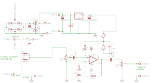
Reviewing a preamp design – I got help from an audio guru to build this circuit in the past. I used it once but I got the circuits mixed up and had to redraw it. I built it just now but I am getting some humming out of it. How does this look to you? Read more
Weird issue with multimeter measuring house AC voltage – When I am measuring house AC, I have one probe in the hot line and the other probe just in the air and not connected to anything but the meter shows up as 10 AC. Why? And why are ground and neutral connected together? Read more
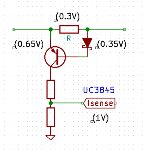
Low voltage drop current sensing – I want to use UC3845 as a control circuit for a DC-DC converter but I want to make some changes regarding the current sense circuit. My requirements are as follow:
(1) high side current sensing (using a shunt resistor)
(2) low voltage drop across that shunt resistor (low power dissipation)
(3) a cheap (no opamps and such) solution
I’ve designed a circuit like this:
Is there any way to further reduce the voltage drop across the shunt resistor? A voltage drop of 0.1V would be nice. Do I have to play with BJTs (maybe Darlingtons) and various diode types to aquire that small (0.1V) difference? Is there any other simple solution for this? Read more
Driving a brushless DCv(BLCD) motor with high-speed (sensor based driving) – I started to hack a BLCD from a CD/DVD ROM set and found out it has three linear Hall sensors and three sets of coils. Each Hall sensor has two outputs and the BLCD motor has three wire, so I use one output of each three Hall sensor and I use and ADC to read Hall sensor voltage and compare them together to find out the correct position of rotor. But the highest speed I can get from the motor is about 2400 RPM and that is not a significant speed for a BLCD motor compared to 8000 RPM and higher that they operate in. Read more
Ways of managing the Li-Po battery – I am designing an open source computer and have been looking for the simplest way of managing the battery which consists of three functions:
1) managing the charging of the battery
2) Regulating the output to 3.3v
3) providing accurate battery level to the processor (gas gauge).
I have not found any solutions that can do all this in one chip or, for that matter, less than three (one for each of these functions). Does anyone know of a good, simple solution? Read more
Constant PV output – I want to do a project for a solar panel. The idea is to keep the output of PV constant by using boost converter for a DC application. Read more
Battery calculations for the microcontrollers – I am developing a project where I have to use a battery of any capacity. The microcontroller will send signals every 100ms (data transmission time would be only 100μS in 100mS). Transmitting current will be 22mA MAX. I want to calculate required battery capacity for 300 days (Daily circuit will be on for 8 hours). Read more
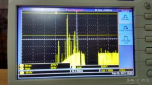
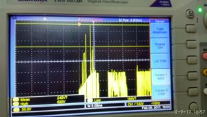
Help to avoid the start up problem in TOPSWITCH-based battery charger – I have designed the circuit from Power Integrations. My problem is when I switched on the supply on direct AC with 50% load, my TOPSWITCH is blasting. When I am trying to turn on with the help of Variac, it is working properly and taking 1.4 A of load. Below are the startup waveforms. Read more
Half-bridge gate drive power requirement – My SMPS worked and all was ok until I needed a small repair and accidentally blew my switching IGBTs. I replaced them with new ones of a different kind but before turning them on I checked whether all is ok with my gate drive ICs. I replaced the IC (IR2110) and checked the supply voltage which is 18 V and it stabilized with the help of 7818 V regulator transistor. As soon as I added the gates to the IGBTs, I switched on the SMPS and it doesn’t work. I measure the gate voltage supply and it has fallen as low as 5 V which is below threshold so the IC doesn’t drive the IGBT gate in order to save it from half-open failure. I can’t understand what has gone wrong. Read more


Leave a Reply