eGaN FET technology is playing a role in making wireless power practical for a variety of home appliances.
Michael A. de Rooij, Yuanzhe Zhang, Efficient Power Conversion Corp.
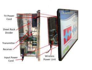
Televisions can get their content wirelessly, but there is one set of wires they still need: those in their power cord. The consumer electronics industry has floated ideas for freeing TVs from their power cords, but this goal remains elusive. There are several reasons, such as the difficultly of meeting high-power requirements for large-screen TVs and the need for identifying an economical technology. Nevertheless, eGaN FETs could play a role in making TVs truly cordless devices.
There are two widely used forms of magnetic field-based wireless power transfer techniques: inductive and highly resonant. Each has advantages and disadvantages. The inductive method relies on the creation of a transformer that can be spilt into two pieces and requires magnetic materials to enhance coupling. This method is used over a wide power range from a few watts for smart phones to several kilowatts for automobile charging. The resonant method makes use of resonance to enhance the coupling between the transmit and receive coils and can be realized with or without the use of magnetic materials. The enhanced coupling allows for designs with more spatial freedom and larger distances between the coils.
At lower power levels wireless power is governed by two standards; Wireless Power Consortium (Qi) and AirFuel. Both these standards have yet to reach the power level required for large screen televisions. The Qi standard requires good alignment between the coils and is limited to 60 W (standard under development). The AirFuel standard can accommodate larger spatial variations making it more suitable for everyday practical situations but it, too, is currently limited to 70 W. However, due to improved use case for the AirFuel standard it will be used as the foundation for this work.
Drafting realistic expectations
The television for this example was a 43-in. Vizio model D43-D1 that is HD capable. Tests revealed that in standby mode it draws less than 5 W, but it immediately increases to 85 W once turned on. This was the highest power drawn regardless of setting, and the set always required this power for at least the first 12 seconds after being turned on. User settings such as brightness would vary the power drawn by the television the most. Under normal operation the nominal power drawn was around 67 W.
The ultimate goal is to embed the wireless power receiver inside the television. This essentially eliminates the high-voltage ac power factor correction circuit and can reduce the cost and size of the TV power supply. It also lets the low-voltage electronics grow thinner, supporting the marketing trends of newer TV models.
Because the internal power supply of the television is always a high-frequency switching converter, it can potentially operate from a dc voltage. Testing confirmed this when the television was powered using 110 Vdc. DC operation significantly simplifies the design of the receiver circuit and reduces the amount of bulky expensive storage capacitors needed.
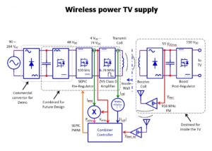
The design starts with a block diagram overview for the entire system. First, an ac-to-dc converter provides a fixed dc voltage from which the wireless power amplifier is powered. Next is a wireless power amplifier that drives the highly resonant coil set. The amplifier comprises a pre-regulator and high-frequency amplifier — which in this case is a SEPIC (Single-ended Primary-Inductor Converter) — and a differential-mode class D amplifier.
On the receiver side is a high-frequency rectifier followed by a boost converter that provides the fixed 110 Vdc for the television circuits. Due to the high power capability of the transmitter, and lack of high-frequency high-voltage diodes for the receiver rectifier, it is important to feedback the unrectified voltage (VRect) to the controller of the transmitter to prevent over-voltage of the output diodes under light loads.
On the transmitter side the coil current (Icoil), the dc supply voltage to the amplifier (Vamp), the amplifier power (Pamp) and the isolated output rectifier voltage (VRect_iso) serve as feedback signals for the combiner controller to regulate the SEPIC converter. The controller determines which of the feedback signals is at its set point and regulates to that set point. There will always be at least one control signal in limit.
Power circuit design requirements
The power circuit design begins with the receiver output stage in that the power for the television is known, and the efficiency of each block in the chain will need to be accounted for to determine the power requirement for each of the blocks.
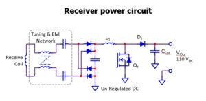
Consider the power circuit of the receiver stage. The final stage is a boost converter with a 110-Vdc output. Its efficiency is estimated on the low side to be 95%. This means the rectifier must deliver 89 W. The rectifier diodes must have a low voltage drop, no reverse recovery, low capacitance, and be able to operate at 6.78 MHz. The only diode able to do this is the 60-V rated PD3S160 Schottky diode from Diodes Inc. To deliver 89 W, the rectifier output voltage must be as high as 55 V. The diodes require a heatsink.
For the transmitter, a differential-mode ZVS class D amplifier drives the tuned coil and is well documented as a robust amplifier when used in highly resonant wireless power applications. The efficiency of the wireless power stage that includes the ZVS Class D amplifier, coil set, and rectifier is approximately 85%. This means the pre-regulator must be capable of delivering 105 W. The chosen topology for the pre-regulator is the SEPIC converter as it can buck and boost the input supply voltage and has proven to operate well as a source for the ZVS class D amplifier.
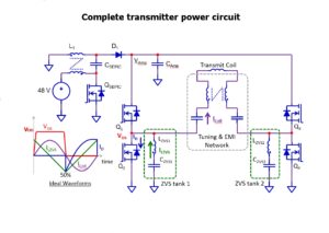
The source for the pre-regulator is an ac-to-dc converter. The design of this converter falls outside the scope of this project as a standard off-the-shelf unit with a 48-V output will be used for experimental verification.
The transmitter has three of the four feedback measurement signals for control. The receiver rectifier output voltage must also be included in the control loop as explained earlier. This voltage, however, must be provided to the transmitter wirelessly. A 916-MHz frequency modulated RF link is provides this wireless link and completes the necessary building blocks for the wireless TV.
The coil-set is critical in the wireless power chain. Large coils tend to be more sensitive to impedance shifts resulting from misalignment, load changes, and the presence of large metal objects. Some larger coils are designed as two interleaved windings that can be connected either in series or parallel. Series-connected coils are more suitable for use with a large distance between the coils. Connecting the coils in parallel significantly reduces impedance shifting but reduces the effective distance for higher power transfer.
In this evaluation, we chose the NuCurrent R36RXTxD1 AirFuel class 4 coil for both the transmitter and receiver, and the windings connected in parallel. These coils are large enough to operate efficiently over a distance of two through 12 in. But for the purpose of this work, the spacing was fixed at two inches based on amplifier power limitations of the prototype.
The transmitter used a modified EPC9512 wireless power amplifier. In this case the SEPIC converter was modified to operate from 48 Vdc and at higher currents. Also included was the RF link to feedback the receiver rectifier voltage. The SEPIC converter output directly powers the ZVS class D amplifier and uses the 200-V-rated 43 mΩ EPC2019 device. The ZVS class D amplifier used four 100-V-rated 105 mΩ EPC8010 devices.
The SEPIC controller has set points of Icoil_max = 1.72 A; Vamp_max = 71 V; Pout_max = 110 W; VRect_iso_max = 53.5 V. On the receiver side, the SEPIC converter was modified on an EPC9512 board to function as a boost converter with 110 Vdc output. It also uses the EPC2019 eGaN FET. A rectifier board was fitted with a heatsink for the diodes and multiple TVS clamp diodes (Vclamp = 57 V) for additional over-voltage protection. The TVS diodes are highly dissipative and are meant as protection in the event the RF link fails. Tests revealed the TVS diodes were unnecessary.
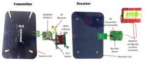
As a precaution and because of the potentially high power drain during turn-on of the TV, a fan provided cooling air for the SEPIC converter FET and diode, and for the receiver rectifier diodes under the heatsink. The output boost converter needed no forced air cooling.
In real life, the transmitter is meant to sit behind a wall. The receiver unit can ultimately be integrated inside the TV. Installation of the television would become as simple as hanging a picture on the wall. The prototype demonstration unit was completely wireless including using WiFi, or WiDi for the image signal.
The prototype revealed that the rectifier diodes of the SEPIC, boost and high-frequency receiver are the sources of the highest losses of any semiconductor component. This reality is driving future designs to focus on synchronous rectification for efficiency improvements.
The EPC9512 wireless power board amplifier was originally designed for 33 W. The FETs on this amplifier are underrated for the power required, and performance improvements when using lower RDSon FETs can be expected and will form the basis for future work.
References
[1] A. DeNisco “CES 2017: Dell brings wireless charging to laptops with the Latitude 7285“, techrepublic.com, January 6, 2017, [Online]
[2] “System Description Wireless Power Transfer,” Vol. I: Low Power. Part 1: Interface Definition, Version 1.2, June 2015.
[3] A4WP Wireless Power Transfer System Baseline System Specification (BSS), A4WP-S-0001 v1.3.1, February 25, 2015.
[4] Diodes Inc., “PD3S160 – 1.0A Surface mount Schottky barrier rectifier,” PD3S160 datasheet, September 2012, [Online]
[5] A. Lidow, J. Strydom, M. de Rooij, D. Reusch, “GaN Transistors for Efficient Power Conversion,” Second Edition, Wiley, ISBN 978-1-118-84476-2.
[6] M. A. de Rooij, Wireless Power Handbook,” Second Edition, El Segundo, October 2015, ISBN 978-0-9966492-1-6.
[7] M. A. de Rooij, “Performance Comparison for A4WP Class-3 Wireless Power Compliance between eGaN® FET and MOSFET in a ZVS Class D Amplifier,” International Exhibition and Conference for Power Electronics, Intelligent Motion, Renewable Energy and Energy Management (PCIM – Europe), May 2015.
[8] M. A. de Rooij, Y. Zhang, “eGaN® FET based 6.78 MHz Differential-Mode ZVS Class D AirFuel Class 4 Wireless Power Amplifier,” International Exhibition and Conference for Power Electronics, Intelligent Motion, Renewable Energy and Energy Management (PCIM – Europe), May 2016, pp 304 – 311.
[9] “Single-ended primary-inductor converter,” [Online]
[10] Efficient Power Conversion, “EPC9509 : 60 V ZVS Class-D amplifier board for wireless power transfer systems,” EPC9509 – Development Board, [Online]
[11] Efficient Power Conversion, “EPC2019 – Enhancement Mode Power Transistor,” EPC2019 datasheet, June 2014 [Revised September 2015], [Online]
[12] Efficient Power Conversion, “EPC8010 – Enhancement Mode Power Transistor,” EPC8010 datasheet, December 2013 [Revised January 2015], [Online]


Given that even the smallest of the “big screen ” televisions is not at all portable, adding a wireless power feed is one of the dumbest exercises that I have seen presented in quite a while,it is on a par with a texting holder for the steering wheel in cars. Really, what was the designer thinking??? What possible benefit , aside from some theoretical status symbolism, could it possibly provide?
Please recall that It is too soon for April fools articles,.
I disagree. I believe that people born ten years from now will not remember a time when home appliances had ac power cords. To see such a thing, they might have to visit the Smithsonian.
I agree with William. If a person’s drive for ‘cordlessness’ is so extreme that they want to hide their TV’s wall-mounted cord, why not install a standard duplex outlet high on the wall, just behind where the TV is to be mounted. Just think of the vast savings to be enjoyed by installing that outlet versus the crazy-expensive, bleeding-edge in-wall wireless power inducer that might or might not work with all such-equipped TVs and, if not present in a TV, would still require a cord running up the wall – or that simple high-mounted outlet I initially mentioned
I completely agree with Mr Teschler above.
Mr K, seems to suffer from a lack of imagination that has plagued pretty much every new invention since the beginning of time.
This will be a big innovation in the TV world
Just because an engineering challenge can be accomplished does not mean that it delivers any actual value. This is especially true for adding a fair amount of complexity to a system package that gains no advantage at all from the added cost and complexity. Consider that that wireless power transmission will need a good deal of additional effort to prevent the circuitry from producing enough interference to cause poor reception. The reality is, and always will be, that wireless transmission of power is less efficient than a wired connection. That is inescapable, no matter how badly anybody wants it to not be true. Next, there is the inescapable fact of that wireless energy field adding to the ambient electromagnetic noise level. That is also inescapable. But the fact that will kill the wireless power fad is that it will add to the price, and in the fiercely competitive consumer products market. that is a fatal flaw, since the wireless power feed delivers no benefit aside from some ego thrill for those addicted to such foolishness..
If we reach g a time when electrical appliances don’t have power cords it will probably be because there is no power distribution network because it was destroyed in the war.. Or, moire likely, power generation has become severely restricted in the name of sustainability. When the population has lost most of it’s freedoms and all are living crowded lives in the city in government mandated small apartments, because that lifestyle is more sustainable, most power consuming appliances will be a luxury that the majority can not have. That is the vision of the future that would have all appliances being cordless. Not nearly as pretty as a power cord on an appliance.
That is how I imagine the future if folks with lots of imagination butwho ignore reality run the show.