Peer-to-peer, engineer-to-engineer questions and answers from the EDABoard.com engineering community around power electronics. Click the “Read more” link and follow the entire conversation and maybe add your two cents by logging in to EDAboard.com
Booster converter circuit – I am working on booster converter project and I chose my switching device MOSFET IRFZ44N. My input is 2-3V and I want the desired output as 10-15V. Will my MOSFET turn on for this input will my circuit work? Read more
AC to AC converter in a small package for converting 220v to 110v – I have an appliance that I’d like to install on the wall on my bedroom. It’s a Broan exhaust fan. The unit only operates using 110 V and my system provides 220 V. Read more
H-Bridge heating without load – I am testing an H-Bridge circuit and it is heating up without load. The MOSFET is IPD60R180C7 (600V, 180 mOhm Infineon MOSFET). Supply voltage is 250VDC and switching frequency is 100KHz. There’s 10nF MLCC immediately close to the bridge and another 100uF electrolyte further away. Trace width between gate and driver is approximately 60mm but nearly differential. Read more
Simulation buck converter – I am trying to solve a homework problem on the subject of Power Electronics (DC-DC Converters–Buck Converter). My question is how to properly set-up this circuit in Pspice because my waveforms look incorrect. I have provided the link to the Pspice files and the image of the desired waveforms from the book. I believe my problem is in the Vpulse parameters; however, I do not have enough experience to understand what exactly to change. Read more
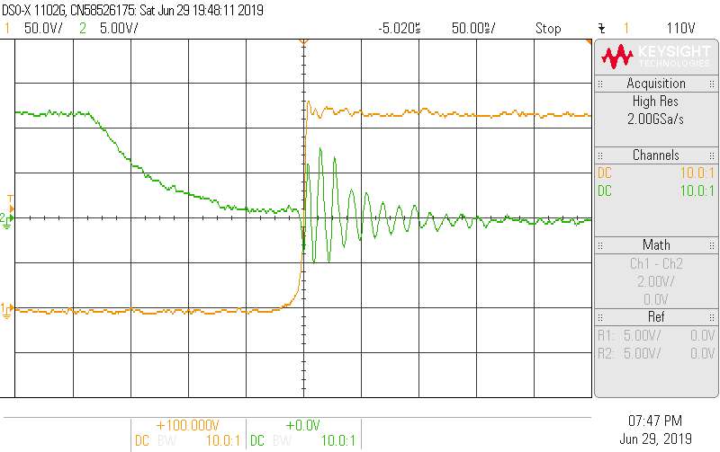
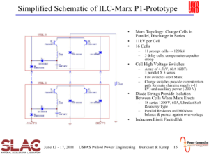
What’s an “isolation diode”? – I came across an interesting powerpoint presentation. As it’s usual with PPTs they don’t give detailed info, so I’m wondering how that isolation diode (on the right connected to the -300V) is working and what is it isolating against and how it is connected to the circuit? Read more
H-bridge 100khz recommendations – Currently, I need a DC to AC inverter that will have an output of frequency 100khz. The input is 12v DC & 0.5A.
This is for wireless power transfer purpose. The flow diagram is: 12 VDC 0.5a > inverter 100 kHz > tx coil || rx coil > rectifier > load (12v 0.5 A max)
1) May I know the recommendation of the MOSFET model that is suitable for this? PWM will be generated by Arduino.
2) Also is there a built H-bridge that I can buy off the shelf and just program the frequency? Read more
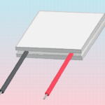
Powering Peltier module – I have tried to power that Peltier module with an AT power supply but I reached max -10°C or something. So I ordered a 12V 10A power supply.
As I measure the Pelletier module, it really does not go up to specs barely -20°C (should <-30°C) and current is only half of the specified current Peltier. Read more
LM3940 (3.3V reg) cannot supply 9V buck-boost – I use a 3.7V 16850 cell that gets boosted to 9V (board : https://www.aliexpress.com/item/3284…27424c4dSXahMo)
As I sometime, have to recharge my cell, I thought I’d use 3.3V coming out of an LM3940, but the booster output drops to 4.4V while the output voltage of the LM3940 drops from 4.0V to 2.2V. Read more
Linear led current regulator – We are seeking a linear LED current regulator. We need it to be an error amplifier on a chip but the drive FET will be external, and the reference to the internal error amplifier will be input from an external source. We can’t find anything off-the-shelf, and Digikey etc. don’t allow us to sort on our requirements. Does anyone know of anything? The current sense resistor will also be external. Read more
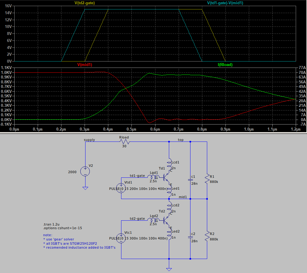
Voltage sharing for IGBT’s in series – I read and simulated the following application note http://www.ixys.com/Documents/AppNotes/IXAN0057.pdf What I can’t understand is why it takes a long time (300nS) for the current in the load to peak AFTER the IGBT’s are turned ON? Read more




Leave a Reply