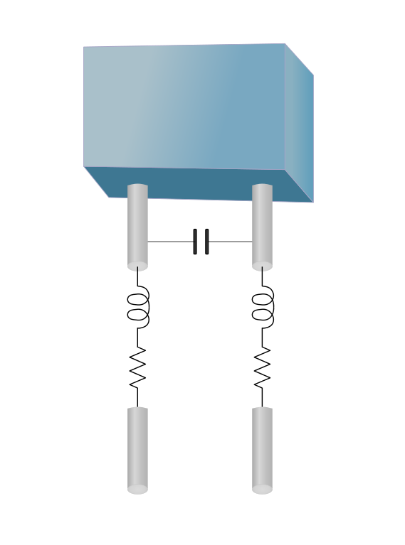
When two electrical conductors are physically close, carry a charge, and there’s a voltage potential between them, they create a virtual capacitor between them, even if the conductors are insulated. The virtual capacitor between them is known as parasitic or stray capacitance.
This can happen anywhere but is most troublesome between traces on printed circuit boards, especially when high-frequency signals are involved. In general, the capacitance is inversely proportional to the distance between the conductors. For PCB traces, it’s a good idea to route conductors such that parasitic capacitance is less likely, but parasitic capacitance can form between a conductor and a ground or power plane, between wires, and between a wire and the wire’s shielding. Parasitic capacitance can form between a transmitting antenna and the earth. The value of the parasitic capacitance is determined using the formula C= q/V, where C is the capacitance in Farads, V is the potential or voltage in Volts, and q is the charge in Coulombs.

Resistors (or anything with resistance with respect to electrical charge) possess a parasitic capacitance that behaves like a capacitor in parallel with the resistive element. Actually, the distribution of the electrical charge is responsible for the parasitic capacitance, and the same charge distribution is responsible for conduction in a resistor in the first place. If the rate of change of the electrical charge is small, the effect of parasitic capacitance can be neglected.
However, the effect of the parasitic capacitance on a feedback resistor, for example, can make a big difference. Miller capacitance is the parasitic capacitance that’s formed in the feedback loop of an operational amplifier. The effects of the parasitic capacitor in the feedback loop are such that the effect is amplified by the op amp; this is known as the Miller effect. It’s true that integrated chips provide more advantages than saving space; the design expertise that goes into integrated chips for the most hackneyed designs is also valuable.
Displacement current
Electric fields that change and exist between charged bodies will cause something like current flow, called displacement current, such that a change in the electric field on one body affects the electric field on a nearby body. The idea of displacement current first appears in Maxwell’s equations and has the same units as electric current but is a time-varying electric field more than an electric current made up of moving charges. It’s easier to understand how a capacitor can appear to conduct current even at low frequencies if you know about displacement current. At high frequencies, the picture changes.
Parasitic capacitance at high frequencies
At higher frequencies, current flow is impacted by parasitic capacitors because capacitors become increasingly better conductors as frequencies increase. Another formula shows the relationship between current, capacitance, and the rate of change in potential (voltage) over time (a.k.a frequency): where i is current, C is capacitance, and dv/dt is the rate of change in voltage over time (frequency). The above formula shows a relationship between current flow, capacitance, and voltage potential with respect to time. An electrical signal that is constant over time and does not change is a Direct Current (DC), and therefore dv/dt = 0 since there is no change in the voltage potential over time. Regardless of the amplitude of the DC voltage, a constant voltage yields no current (i = 0) from the above formula, and thus the capacitor behaves like an open circuit. A battery driving a circuit loop will see a capacitor in that loop as an open circuit as if the wires were cut. But if you have a change in the voltage potential (the voltage amplitude varies with time), the frequency of the amplitude changing affects the current flow, and dv/dt converges to a value. Looking at the above formula, if dv/dt is a value other than zero, then current flows.[i]
The higher the frequency, the more the capacitor conducts like a resistor approaching a short circuit. At an infinite frequency, the capacitor acts like a wire. Therefore, parasitic capacitance is a real problem at high frequencies since its effects don’t really affect things much at lower frequencies. However, parasitic capacitance experienced at high frequencies unexpectedly connects the reference plane of a PCB to the chassis, among other things. Note that parasitic capacitance will form between any conductive body that carries a charge; therefore, parasitic or stray capacitance can form between an antenna and the dirt/earth/ground (and more so if the ground is wet and therefore more conductive). Parasitic capacitance can form between a metal table and a PCB sitting on top of it (but less so with a table made from an insulating material). Circuit design for high frequencies means that additional attention must be put into the design, especially with respect to PCB layout or placement of any conducting body with respect to another conductive body.
[i] PDF: Capacitors and inductors, PI Hutchinson, 2004, MIT.edu


Hello,
I am using LT spice to reverse engineer a photovoltaic and rechargeable charge management circuit for a 9 parallel LED by 16 series light tree that I found fly tipped.
The LED forward voltage is such that the arrangement is 9v x 3
. https://www.mypostshop.com/Images/product/PDF/2/Tech_spec/ENG/AR791.pdf
The parasitic capacitance of the battery is not listed.
How can I search the internet for this parameter?
Faithfully
Kieran