Both switchers and LDOs have their place in power distribution, as each has special attributes.
With few exceptions, every electronic circuit needs at least one well-regulated, accurate, stable dc power rail at 12, 5, 3.3 V, or even at 1 V, and many systems need five, ten or more such rails. This power must come from regulators (aka converters) which are the last stage in a chain which began with a higher-voltage ac/dc or dc/dc converter, and which first provided an intermediate dc-bus voltage. This intermediate voltage is typically between 12 and 48 V, depending on the design and some legacy issues. (For low-voltage battery-operated devices, there is often no intermediate stage, as the battery pack provides a mid-range dc voltage which must be regulated.)

There are two ways to regulate the lower dc voltage to the final rail voltage: Use either an LDO (low dropout regulator, often called a linear regulator) or a dc/dc switching converter (also called a switcher or switch-mode power supply–SMPS). LDOs and switchers operate using entirely deferent principles. In simplified terms:
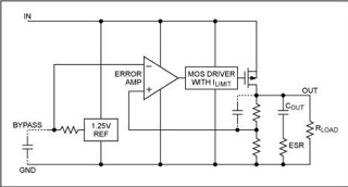
The LDO has an internal voltage reference (the desired output value), an op amp functioning as an error amplifier, and a pass-element power MOSFET. The op amp compares the actual dc output to the desired value and drives the MOSFET (which is modulating the unregulated input dc rail) so as to keep the MOSFET supplying current at the target voltage. This is a classic all-analog, closed-loop topology
The switching regulator takes the unregulated input-dc rail, and “chops” it at a frequency between 50 kHz and several megahertz (depending on specific model), and passes this ac-like power rail through a transformer or a switched-capacitor arrangement to step the voltage up or down. The output is rectified and filtered to get rid of the ripples caused by the chopping. It is then compared to the desired voltage (again, from an internal reference) while the switching duty cycle is adjusted to keep the actual output voltage at the desired value.
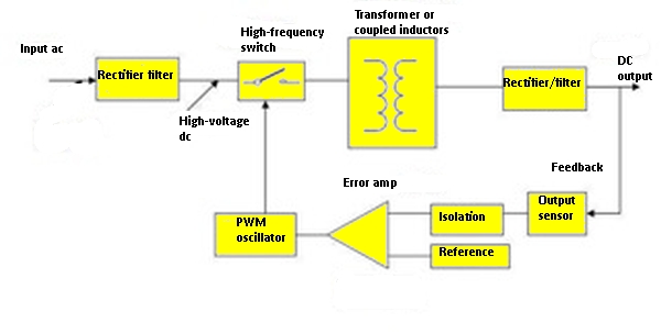
Practical LDOs and switchers add many circuit enhancements and innovations to add protection and improve performance, accuracy, stability, line and load regulation, and other key parameters; these are important but invisible to the user.
Though the LDO and the switching regulators perform the same function, they have quite different attributes.
The LDO:
• Is easy to use; just drop it in where needed and add one or two small ceramic capacitors, as called out by the vendor;
• Is low noise, as it is an all-analog circuit with no switching action;
• Is viable for output current from under 100 mA to several amps;
• Cannot boost the input-rail voltage, but can only regulate it down (call “buck” mode);
• Has typical efficiency between 30-70%;
• In addition to usual power-supply/converter parameters, has a specification called the dropout voltage. This the lowest value of the difference between unregulated dc-input rail and the dc output at which the LDO can still function; a smaller value is better.
• Efficiency is a function, in part, of the difference between input-dc and output-dc voltages, so the lower this value can be set, the better.
The switching regulator:
• Is viable as an IC or tiny module up to about 10 A; above that, it requires more and larger components, but is still the dominant regulator design;
• Can either be designed to boost the output, buck it, or even do both seamlessly, which is useful in cases such as driving a 1.8-V rail from a single battery which goes from 2.2 down to 1.2 V in use;
• Efficiency is in the 60 to 95% range, and is a function of design and of load;
• Are noisier than LDOs because they are switching devices; the noise fundamental is at the switching frequency. Some regulators are designed for low noise, almost comparable to LDOs, but this may require a tradeoff in other performance aspects;
• Are available in a wide array of variations in internal topology, each optimized for a different aspect or operating mode, such highest efficiency at low duty cycles);
• A given switcher IC can be tailored for smaller total footprint, but at reduced efficiency, by moving the operating frequency into the MHz range.
As in almost all engineering decisions, the decision about where to use which approach depends on the application. Here, it depends mostly on the maximum output-current level, as well as the overall power-distribution topology (tree).
If the output current is over a few amps, the switcher is almost always the first choice, primarily because of its efficiency, which is related to power savings and thermal dissipation. Below a few hundred milliwatts, the LDO is often the better choice, because its inefficiency relative to the switcher is often negligible. In the mid-range, it may be a close call, but the switcher usually makes sense.
However, this analysis presumes that a single regulator is all the system needs. In reality, today’s systems often have five, ten, or more distinct rails, each with different current ratings, tolerances, regulation requirements, and noise ratings. For this reason, many systems use the intermediate bus of 15-48 V to drive both switchers and LDOs. The LDOs may actually be sourced by yet another lower-voltage intermediate-voltage converter, to reduce to input/output differential.
Most designs now use a switcher to provide the higher-current rails but also add many highly localized LDOs to directly supply power to the pins of individual ICs. These close-in LDOs isolate their IC loads from both switcher noise and picked-up (EMI) noise, while providing tight regulation at the exact voltage needed. This approach also works well when an IC (such as an FPGA) or subsection needs many lower-current rails, which often differ from each other by only a few hundred millivolts.
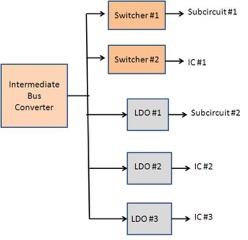
The decision about how to mix LDOs and switchers is complex, balancing many parameters and tradeoffs; there is no right or best answer. The choice of which regulators to use where and when, and in what combination, is a function of multiple design priorities and technical factors.



Leave a Reply