In part 1 of the FAQ, we looked at techniques for a modest amount of boosting of lower voltages, as well as for increasing a voltage to a much higher value.
The techniques discussed thus far boost and thus multiply the voltage, but what are called voltage “multipliers” usually give push voltages to much-higher values. The design and considerations change dramatically when the output voltage starts going about 100 V and then into the >1000 V range. Fortunately, many of these higher-voltage systems need only modest current (100 mA or less) while simplifies the problem somewhat.
Q: Why can’t you just use a transformer with suitable turns ratio to multiply the input voltage by 10× or 1000×, or whatever is needed?
A: In theory, you could. But as the turns ratio and secondary voltage increases, there are issues of additional inefficiency due to transformer losses (perhaps acceptable), and high-voltage breakdown of the wire insulation, among other issues. This does not mean it can’t be done, but it can be a difficult approach due to practical considerations.
Q: Has the transformer approach been used commercially?
A: Yes, it has been used successfully in a configuration called a flyback converter in many applications (Reference 3), such as for the cathode-ray tube (CRT) of the mass-market TVs which dominated the video world for over 50 years (until the LED/LCD flat panels took over). The flyback design uses a special transformer which is a wound as a combination of a transformer, plus an inductor to store energy.
Q: So, what else be done to develop higher voltages?
A: There are various topologies which use passive components to multiply an input voltage. In general, they rely on a combination of diodes and capacitors in a series of stages. These stages leverage the voltage of the previous stage.
Q: What is the general framework of these circuits?
A: These voltage multipliers are specialized rectifier circuits which develop an output voltage which is (in theory) an integer times the AC peak input, for example, ×2, ×3, or ×4 times the AC peak input value. They are usually configured as a stack of half or full-wave rectifiers.
Q: Can you show an example?
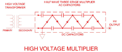
A: The circuit of Figure 1 shows a three-stage multiplier. The action is as follows: each cycle of the AC input charges the various capacitors, and each capacitor is eventually charged by successive AC cycles to the peak value of the input sine wave. Thus, for a 120 VAC rms line voltage, the peak is 170 V. By doing this across the multiple capacitors – each charging independently – and then allowing these capacitors to be stacked in series, the output voltage is the sum of the individual capacitor voltages.
Q: But there is no tangible or visible switching in this arrangement, so how does it go from charging to stacking of stored voltage?
A: It uses a standard rectifier arrangement. The diodes act as passive switches and prevent discharge of the capacitors when the input voltage starts to drop. They allow current flow to the capacitors, but not flow from the capacitors back to the input source.
Q: What if I need a negative high voltage from a multiplier?
A: That’s the only easy thing about high-voltage multipliers: simply reverse the polarities of all the multiplier diodes and capacitors to produce a negative voltage multiplier.
Q: Sounds easy enough, but is it?
A: Absolutely not! First, the diodes and capacitors must have a minimum reverse-breakdown voltage rating of at least twice the peak voltage across them. Even if you are starting with a 120 VAC line (170 V peak), you’d need components rated for at least 1700 V if you are building a 10× multiple (plus a factor of ×2 or more for a safety margin, of course).
Q: What are some of the other issues in high-voltage designs such as these?
A: First, they can deliver very little current at that high voltage: once you begin to draw current for the for the load, the stored charge and thus the voltage drops. In many cases, this is too restrictive, since many higher-voltage applications need only a small amount of current, for example, to create an electric field.
Q: Any other issues?
A: There are many, as the physics of the high-voltage world has many points at which “strange” things happen; increasing the voltage is not a linear situation (think of it as analogous to water crossing the freezing point). For example, high voltage circuits will have corona discharges from sharp points. These are both hazardous in themselves, and they also cause pitting of metal contacts and can punch through insulators. Even “small things” such solder joints are an issue for corona.
Q: How so?
A: You might assume a standard, well-made solder joint would be OK, but it will act as a starting point for corona discharge. Therefore, “ball soldering” is frequently used instead in the high-voltage implementation using large, spherical solder connections (Figure 2). The large-diameter, smooth spherical shape of the solder connection helps to control the local E-field, thus suppressing the generation of a corona.

Q: Should I build my own high-voltage circuit?
A: Not a good idea, because there is so much more to it than just the schematic and the bill of materials (BOM), and that BOM itself has truly unique parts. It is a very dangerous world where just “being careful” is not enough, and even the slightest mistake or oversight has deadly consequences. Physical spacing, component ratings, insulation properties, pinhole imperfections, and material breakdown are just some of the many issues. Circuit protection is also unique: specialty fuses and other overvoltage/overcurrent devices are essential.
Q: Sounds like no one is doing these, right?
A: Not surprisingly, that doesn’t stop people from doing so, as seen in the posting which shows someone building a multiplier going into the tens of kilovolts (Reference 7). Don’t try this at home (or even in the lab) unless you have someone with you is experienced in high-voltage construction (and can call for help – although it usually too late at that point!). Finally, there are the complicated regulatory issues if you intend to produce and sell the product.
Q: Can you give an example of a high-voltage multiplier used in a recent, attention-getting project?
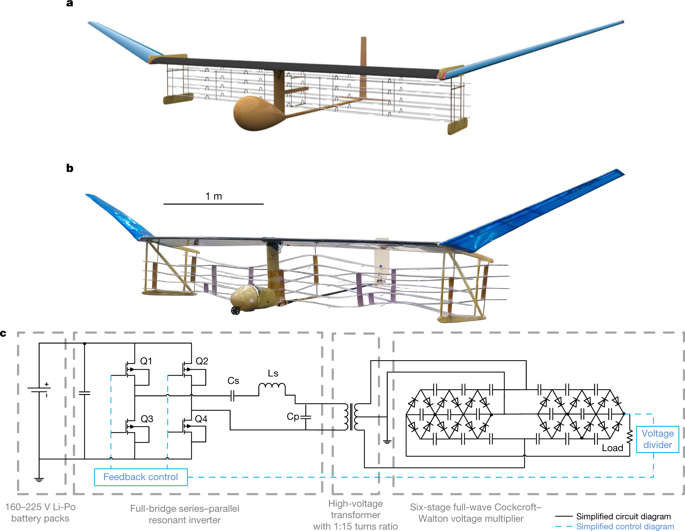
A: Yes, indeed. A team at MIT recently built and tested an aircraft with a wingspan of a few meters but with no moving parts (details are in References 8 and 9), (Figure 3). Instead, it uses the flow of negative ions attracted by high-voltage, a positive electrostatic field across the wing rear edge. This non-tethered, free-flying aircraft has an onboard battery (nominally at 200 V DC) for its 600-W power supply (Figure 4, (designed by the Power Electronics Research Group in the MIT Research Laboratory of Electronics). It uses a switching regulator followed by a 1:15 step-up transformer, and then a six-stage, full-wave “Cockcroft-Walton” voltage multiplier to deliver 20 kV DC (see References 10 and 11).

This FAQ has looked briefly at the strange yet important world of high-voltage boosters and multipliers, some of which result in modestly higher voltages, and some which reach into kV range. As voltages go beyond about 60 V, issues of safety become a concern. As they go into the hundreds and thousands of volts, there are additional issues of material characteristics and electrical phenomena which show that design and construction for these levels is a very different world.
References
- EE World Online, “FAQ: What is a charge pump and why is it useful? (Part 1)”
- EE World Online, “FAQ: What is a charge pump and why is it useful? (Part 2)”
- Wikipedia, “Flyback converter”
- Spellman High Voltage Electronics Corporation, “High Voltage Reference Manual”
- Spellman High Voltage Electronics Corporation, “What is a voltage multiplier?”
- All About Circuits, “Voltage Multipliers (Doublers, Triplers, Quadruplers, and More)”
- Instructables, “High Voltage Multiplier”
- MIT, “MIT engineers fly first-ever plane with no moving parts”
- MIT Electric Aircraft Initiative, “MIT engineers fly first-ever plane with no moving parts in propulsion system”
- Georgia State University Hyperphysics, “Cockroft-Walton Accelerators”
- Wikipedia, “Cockcroft–Walton generator”
- Wenzel Associates, TechLib, “Cockcroft-Walton voltage multipliers”

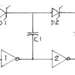

[…] 2 of this FAQ will look at how clever schemes, based primarily on diodes and capacitors, are used to … […]