Part 1 looked at the basics of noise, especially concerning power supplies. There are two noise sources which are not as obvious to many engineers as noise that results from the switching action of the power supply: differential mode noise and common-mode noise. These two noise modes have different causes and thus different solutions
Q: What is differential mode noise?
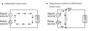
Differential mode noise (often referred to simply as differential noise) is noise which is conducted on the line and neutral wire in opposite directions, Figure 1, left side.

Q: What is the best solution to deal with differential mode noise?
A: A choke (inductor) placed as shown will usually handle the problem. The basic differential mode noise filter uses a single-winding choke which is inserted into the line path, along with a capacitor from line to neutral, thus blocking noise from propagating through the system, Figure 1, right side.
Since the differential mode noise inductor is in the line path, it handles both the noise and the DC offset due to the current being supplied to load. Therefore, it must be designed to provide the needed inductance but do so with low DC resistance (DCR) to handle both the RMS current and the peak line current without saturating. If the current level is low, a chip-style ferrite-bead component can be used.
Q What is done to reduce common mode noise?
A: Again, a specialized inductor is the answer. The basic common-mode noise filter uses a dual-winding inductor in both line and neutral paths, plus a capacitor from line to ground, Figure 2, right side. Since the line and neutral currents pass through the common-mode windings in opposite directions, there is no net DC flux and therefore no possibility of saturating the choke’s magnetic core. The common mode choke only needs to have the required inductance along with sufficiently low DC resistance (DCR) for the RMS current.

Q: Is there a way to tell which type of noise problem is in the design?
A: Yes, to some extent. First, apply a clamp-on ferrite onto a cable, remembering both lines (DC power and ground) will be in that cable. If the noise is reduced, or the immunity is increased, that indicates common mode problem; if there’s no effect, it’s likely a differential mode problem. If there is a common mode problem, try a common mode choke. If it’s a differential mode problem, use a chip bead ferrite or a differential mode choke.
In general, for frequencies above 10 MHz, it is most likely a common mode noise issue, but not guaranteed. It’s possible to have differential noise above 10 MHz, but that doesn’t happen very often.
References
- Radio-Electronics.com, “Resolving EMI common mode & normal mode noise”
- Pulse Electronics, “Understanding Common Mode Noise”
- Murata, “Differential and Common Mode Noise”
- Murata, “Conditions for Electromagnetic Interference and Future Trends”
- Würth Elektronik GmbH, “EMC Basics: Common Mode vs. Differential Noise” (and previous blogs in the series)


[…] A: These two noise sources and their solution will be discussed in Part 2. […]