The need to sense and measure current at one or more points in a circuit is very common. In situations ranging from microamps going into or out of a battery to DC current from a solar panel to feedback for a power supply controller to tens or hundreds of amps of AC power to a house or a power-line branch, it’s important to know the current in order to manage the system, optimize its performance, maintain safety levels, guide performance, and more.
Unlike voltage measurement, which requires touching two probes to a pair of points in a circuit to measure the potential difference between those points, current measurement is more complicated and has more options and tradeoffs.
This FAQ pair will look at the four available, widely used approaches to measuring current. Part 1 will look at two that are suitable for both AC or DC current, while Part 2 will look at AC-only transducers.
Q: What are the options for measuring both AC and DC current?
A: There are four possibilities, each with different capabilities, concerns, and attributes:
- The shunt resistor (also called a current-sense resistor);
- The Hall-effect device;
- The Rogowski coil;
- The current transformer.
Q: How is the shunt resistor applied?
The shunt resistor is placed in series somewhere between the source and load. The voltage across this resistor is then measured via an amplifier, and the current is determined by simply applying Ohm’s law: I = V/R. This can be done digitally (numerically) but is also often done using analog components, a low-cost, fast, and easy-to-interface approach.
The resistor can be placed on the high side, between the source and load, or the low side, between the load and “ground” (Figure 1). It is easier to interface to the amplifier if between load and ground, but doing so causes some system-wide issues in most cases, as it moves the load off of ground. Doing so is often undesirable in terms of mechanical mounting of the load, may cause safety issues, and may affect source/load stability.
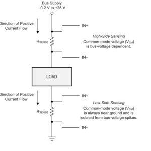
If the resistor is placed on the high side, a differential amplifier is needed to sense the voltage across the resistor properly. That amplifier must also be able to withstand the common-mode voltage (CMV) of being placed on the supply side. Regardless of whether a low-side or high-side configuration is used, the shunt resistor is usually quite small, on the order of milliohms or less, to minimize voltage drop, power loss, and associated heat.
Q: What are some of the features and attributes of this method?
A: Among the key points:
- It is low-cost and conceptually simple, although the interface circuitry does add to the total cost;
- It can be used for AC or DC currents;
- Has modest dynamic range;
- It is not isolated (no galvanic barrier), so isolation circuitry may be needed in some applications;
- The mechanical connection of wires to the shunt resistor is critical, especially at higher current levels (above ~10A);
- Temperature coefficient of resistance and associated changes in resistance value may be a problem in some applications, so special low-temp resistors may be needed;
- Since it is dissipative, it may require a heat sink, which brings the issue of mechanical mounting and isolation from system ground;
- Specialized amplifier ICs are available that work well for this application, including more difficult high-side sensing;
- Is a good fit for battery-powered applications, especially at lower current levels.
Q: What about the Hall-effect device?
A: This sensor is based on a solid-state implementation of a principle of physics discovered in 1879 by Edwin Hall. The effect produces a voltage difference (called the Hall voltage) across an electrical conductor, transverse to an electric current in the conductor and to an applied magnetic field perpendicular to the current, Figure 2.
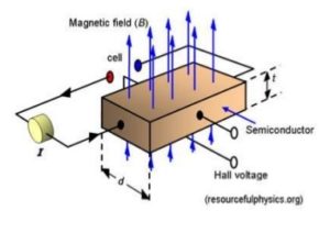
The output voltage of a Hall sensor, made of semiconductor material, varies in response to a magnetic field produced by a current in a wire. The Hall-effect sensor is widely used in automotive applications to sense current going to specific circuits and assemblies, among other uses.
Q: What are some of the features and attributes of the Hall sensor?
A: The Hall sensor is:
- Suitable for AC and DC;
- Low cost;
- Wide range, but mostly used at lower-current levels;
- Electrically isolated;
- Subject to material aging and performance drift;
- Sensitive to temperature change and may need compensation circuitry;
- Requires suitable interface circuitry, which is often integrated into the sensor package;
- Is physically small and has little dissipation, so self-heating is not an issue.
Part 2 of this FAQ will look at two widely used transformer-like transducers, the Rogowski coil and the current transformer, which are restricted to AC measurements.




Bill, your post was informative. I wasn’t aware of how knowing the current could help manage the system. After your explanation, I can see how it also helps optimize performance.