Electromagnetic compatibility (EMC) and electromagnetic interference (EMI) are system-level considerations that have implications for power system design, especially when multiple board-mounted dc/dc converters are used in a distributed power architecture (DPA). EMC/EMI is a multidimensional consideration and includes differential- and common-mode noise on both the input and output of the converter radiated and conducted noise and converter susceptibility and emissions levels.
EMC is defined as the ability for a device to operate as specified even when subjected to various EMI forms within given bounds. Board-mounted dc/dc converters can be a significant EMI source, which must be controlled to ensure proper system operation. And they can be susceptible to interference, especially on the input side.
High-frequency board mounted dc/dc converters allow the size of the magnetic components in the converter to be minimized, reducing overall solution size. The use of smaller passive devices makes it simpler to design a compact circuit, leading to better EMC/EMI characteristics.
However, high-frequency operation can also result in increased EMI from the power switching circuitry in the converter. One of the causes for this is the steep MOSFET switching edge resulting in high dI/dt (depending on the rise time, with a frequency spectrum of up to several hundred MHz), which are influenced by the MOSFET output capacitance, the junction capacitance, and the reverse recovery capacitance of the Schottky diode, and other factors.
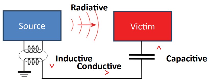
As illustrated above, EMI can take the form of conducted, radiated, or coupled emissions. Depending on the application and the system design, each form of emissions can be a significant concern when using multiple board-mounted buck dc/dc converters in a DPA.
- Conducted emissions are unwanted electromagnetic energy carried into an electronic system via wires, circuit board traces, etc. It can take for form of common-mode or differential-mode (also called normal-mode) energy.
- Coupled emissions consist of electromagnetic energy capacitively or inductively coupled from the source of the interference to the electronic system.
- Radiated emissions are electromagnetic energy radiated through space from the source of the interference to the electronic system.
EMI standards
There are two types of EMC standards, Basic and Generic/Product-related. Like IEC 61000-4 and CISPR 16, the Basic EMC standards do not specify emission limits or immunity test levels; they specify how the measurements are to be performed. The generic EMC standards and product (family) EMC standards such as CISPR/EN 55022/32 and the FCC specify limits and test levels and refer to Basic EMC publications for test setup and methods specification.
Designers of IT and multimedia equipment must meet EN 55022/32 Class A and Class B limits for conducted emissions with quasi-peak and average signal detectors over the applicable frequency range of 150kHz to 30MHz. Both quasipeak and average limits must be satisfied. Products designed for North American markets must comply with equivalent limits established by FCC Part 15. Subpart B sets conducted emissions limits equivalent to those in CISPR 22 and EN 55022/32.

The IEC 61000 Basic EMC standard consists of several parts; General (61000-1), Environment (61000-2), Limits (61000-3), Testing and measurement techniques (61000-4), Installation and mitigation guidelines (61000-5), Generic Standards (61000-6), Miscellaneous (61000-9).
The CISPR 16 Basic EMC standard consists of four parts: CISPR 16-1 has six subparts and specifies voltage, current, and field measuring apparatus and test sites. These include calibration and verification aspects of the measuring apparatus. CISPR 16-2 has five subparts and specifies the methods for measuring high-frequency EMC phenomena, dealing with disturbances and immunity. CISPR 16-3 is an IEC Technical Report (TR) that contains specific technical reports and information on the history of CISPR. CISPR 16-4 includes five subparts and contains information related to uncertainties, statistics, and limit modeling.

Controlling EMI
Controlling EMI is important for two reasons; systems that don’t meet the appropriate EMI standards outlined above are prohibited in many markets, and systems with excessive EMI are likely to experience degraded performance. Just as EMI is a multidimensional problem, there are several avenues to pursue working to control EMI. If board-mounted dc/dc converters from reliable suppliers are used, radiated emissions and susceptibility are not usually a problem. However, the converter’s input side needs attention to minimize conducted emissions from the converter onto the power bus and handle the potential for susceptibility to transients from the power bus impacting converter performance. Some general considerations include:
Circuit Design / Circuit Partitioning: Keep current loops small to minimize conductors’ ability to couple energy via induction or radiation and design proper capacitors and other components in the design to minimize coupling issues. Also, using board-mounted dc/dc converters that incorporate Frequency Spread Spectrum with switching frequency jitter can effectively reduce EMI by not allowing emitted energy to stay in any one frequency for any significant amount of time.

Filtering: Place filters as close to the converter as possible. Keep bypass capacitor leads as short as possible. In a typical board-mounted buck dc/dc converter application, input filtering is usually the most critical. There is an inductor between the power MOSFET and the output, at least somewhat mitigating the EMI there. However, EMI on the input side can propagate throughout the system since it will be carried by the main power bus. While the input side is most critical, it is not wise to neglect the output side when considering EMI. It is common for board-mounted dc/dc converter suppliers to list on the datasheet the external components needed to meet specific EMC/EMI standards.
Shielding: There is a rule of thumb that when frequency is lower than 200MHz, grounding might be a viable solution, but when frequency is higher than 200MHz, it creates radiation, and the best solution becomes shielding. For applications such as telecommunications, process control, broadcast, industrial, and test and measurement equipment, board-mounted dc/dc converters with six-sided metal shielding are often recommended to maximize EMC/EMI performance.
In the final analysis, EMC/EMI is a system-level concern. Optimizing the EMC/EMI performance of board-mounted dc/dc converters is an important consideration, but other system elements are often more important contributors to EMC/EMI performance.
The fourth and final FAQ in this series will review the “basics of board-mounted dc/dc converter reliability.”
References
An overview of conducted EMI specifications for power supplies, Texas Instruments
Beginner’s Guide To EMC, EMC Fastpass
Discussion of Electromagnetic Interference, Boyd Corp.



Leave a Reply