Design standards for rail transportation equipment are so severe that they are used as qualifications for products targeting other areas where ruggedness comes in handy. Here’s a quick overview of what these standards entail.
Martin Tenhumberg | Traco Power
In transportation, there is an emphasis on electronic systems in rail because of expanding safety, telemetry and infotainment systems. The move away from fossil fuels to electric drives also adds further opportunities for electronic control.
By the nature of the application, electronic systems in trains are powered from a relatively noisy dc source. Voltage spikes, surges and drop-outs are common, along with radiated and conducted EMI from the high-power transmission systems. Shock and vibration are a constant stress and temperature extremes and swings are normal. The safety of passengers and staff is also of utmost concern. Designers must further consider the flammability of the materials used as well as the smoke and gas emissions that may result.
Other markets face many of the same challenges. Industrial mobile systems, such as construction and material handling machinery and forklift trucks, also see harsh outdoor conditions. Similar requirements apply to equipment for protection and recovery services such as police and fire, snowplows, and electric vehicle charging stations. With no clear standards of their own, applications in these markets typically turn to existing, ruggedized equipment already designed and built to railway standards.
The conditions in such systems may be too much for standard industrial electronics which are often simply commercial grade devices with support for an extended temperature range. They are built with an underlying assumption that their supply rails will be ‘clean’ and that shock and vibration levels will be low.
The rail environment, although harsh, has well defined qualities. Historically, when rail electrical equipment consisted of simple signaling, control, heating, and lighting, power rails were not filtered heavily. The equipment was expected to simply tolerate variations.

Today the situation has improved. One standard, EN 61373, defines the sometimes-harsh shock and vibration environment for different prescribed areas within the train. Other generic standards, such as the EN 61000-4 series for EMC, are also often referenced. Finally, compliance with the British Railway Industries Association standard RIA 12 is often required, including its severe, high energy surges.
EN 50155 is the basis standard for railway electronics, meaning it calls up EN 61000-4, EN 61373, and others. It also applies for most other ruggedized dc/dc converter applications. It defines environmental and service conditions, reliability expectations, safety, design and construction methods. It also covers documentation and testing. Typical industrial-grade electronics might meet the general requirements, but dc/dc power converters must withstand much wider input voltage variation with several possible nominal values.
The variations around each nominal can be summarized as follows:
Continuous range = 0.7 to 1.25 x VNOM
Brownout = 0.6 x VNOM for 100 msec
Surge = 1.4 x VNOM for one second

It is typically not practical to ride through brownouts for 100 msec, and surges of one second have too much energy to clamp. Power converters must therefore operate over the complete range with some safety margin. In practice, this means an input range of more than 2.33:1. Nominal voltages of 48 V and 96 V are also possible, with other French and U.S. ranges having different minimums and maximums. The dc/dc converter manufacturers meet these requirements by offering converters with wider 4:1 input ranges (typically 43 to 160 V) to cover the majority of applications.
Higher voltage, short-duration surges and transients are also specified according to EN 50121-3-2, derived from the basic standard EN61000-4. Fast transients are ±2 kV with rise and fall times of 5/50 nsec and repetition rate of 5 kHz. Surges are ±2 kV line-to-ground and ±1 kV line-to-line with rise and fall times of 1.2/50 µsec from a defined source impedance, ac coupled.
There also may be contractual requirements to meet extended or different specifications, such as RIA 12. This standard requires immunity to surges of up to 1.5 x VNOM for one second and 3.5 x VNOM for 20 msec from a low source impedance of 0.2 Ω. For a 110 Vdc nominal system, this is a peak of 385 Vdc. This level lies outside the normal range of a converter, especially if it must work down to the 66 Vdc brownout minimum. The energy available from such a low-impedance source means that the voltage cannot be clamped by a transient voltage suppressor (TVS).
Depending on the power level, either a pre-regulator on the supply input or a circuit must switch off the input for the duration of the surge. Hold-up in the dc/dc converter must maintain the output during this period. Another requirement, also from RIA 12, is that the supply withstand fast transients of up to 8.4 kV with a trapezoidal waveform spanning 100 nsec from a 100-Ω source impedance. These levels are relatively low energy and can be clamped effectively with a TVS diode or proprietary filters from dc/dc converter manufacturers.
EMI and electrostatic discharge requirements
The EN-61000-4 series is normally encountered as a standard for testing compliance with the EMC directive for ac input power supplies, all of which must have appropriate filtering. Industrial dc/dc converters, however, are normally embedded in electronics and protected from supply-borne conducted EMI.
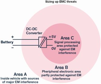
Moreover, dc/dc converters require additional external filter networks because they do not normally include filtering suitable for direct connection to dc rails. EN 50121-3-2 also spells out requirements for immunity to conducted common-mode RF up to 80 MHz and immunity to electrostatic discharge and electromagnetic fields at the enclosure-port level. Conducted emissions follow the requirements of the basic standard EN 55016-2-1.
Railway shock and vibration requirements are tough. EN 61373 defines the shock and vibration tests for rail applications. This standard specifies different categories of locations with rising levels of test severity:
Category 1, Class A, Body mounted
Category 1 Class B, Body mounted
Category 2, Bogie Mounted
Category 3, Axle mounted
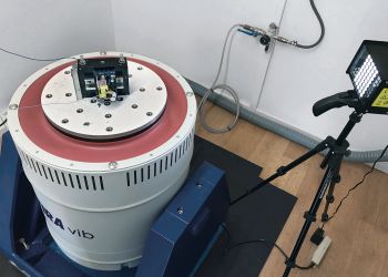
As an example, low-mass items in Class B body-mounted equipment must withstand vibration accelerations of 5.72 m/s2 in the vertical direction at test frequencies between 5 and 150 Hz, with longitudinal shocks peaking at 50 m/s2 (almost 5 g). In the most severe axle-mounted environment, equipment must withstand vibration up to 144 m/s2 (nearly 15 g) and shocks of more than 100 g in any direction.
Operational conditions and more severe long-life stress levels are defined for different mounting orientations. Again, power modules not built to be rugged are unlikely to be adequate. At low power, dc/dc converters housed in SIP-style packages don’t have enough mechanical support. For this reason, the TMR 3WIR and other similar products employ offset mounting pins that – along with encapsulation — provide additional mechanical stability. Larger devices such as the TEQ 300WIR series combat the effects of vibration through the use of spring clamps on the cable connectors, ensuring a stable and long-lasting connection.
Temperature shock and fire safety
Rail applications don’t normally see severe operating temperatures with passenger and cab areas expected to lie at 25°C nominal, rising to 55°C. Equipment cubicles may be at 70°C but, in all cases, equipment must survive an extra 15°C for 10 minutes. Thanks to the optimal design of integrated heatsinks, solutions such as the TEP 150WI and TEQ 300WIR fulfil these cooling requirements.

At first glance, power converters rated for -40 to +85°C seem adequate for most encountered temperatures. Thermal shock, however, is also a consideration. Thermal shock replicates a train or other vehicle entering and leaving a tunnel or building where it may experience 40°C differences at 3°C/sec rates-of-change. This temperature shock may cause sudden condensation.
Power converters for such environments require encapsulation or conformal coating with special precautions against damage from differential expansion rates and thermal shock. The use of nickel-plating, as opposed to gold, for the TEN 40WIR series of dc/dc converters protects against the corrosion that can result from repeated exposure to condensation.
To promote passenger safety in the event of a fire, the materials used in dc/dc converters must also conform to EN 45545-2. The material requirements come from different hazard levels (HL) defined by EN 45545-1:2013. Hazard levels are determined from a combination of the vehicle’s construction and utilization category. Other parts of the EN 45545-2 standard, such as R26 for small electronic products, may also dictate additional product requirements. Tests for oxygen index, flue gas density, and smoke toxicity measure how the product compares to the requirements. The ultimate goal is to minimize the likelihood of a fire and, should one occur, limit its impact on passengers and staff in getting to safety unaided.
Traco Power has addressed the rail requirements with a wide range of off-the-shelf products. Power ratings are from 3 to 300 W.
The PCB-mounted versions support 11 ranges of power and the chassis-mounted units provide nine power ranges. All offer a 4:1 input range with variants that include 43-160 Vdc for 110 Vdc nominal as well as 9-36 Vdc and 18-75 Vdc for 24 and 48 Vdc nominals.

Packages include metal-can SIP8 in 3 and 6-W variants with additional mounting tabs for vibration-proofing; 8 W in a DIP24 package; and industry standard 1×1-in and 2×1-in types for ratings of 10 through 40 W. Chassis-mounted versions are also available from 20 to 300 W. Depending on the model, the converters include input filtering to EN 55032 class B level and feature the ruggedizing and environmental sealing required for rail and similar applications.
REFERENCES
SCI study forecasts upturn in global rail market
TRACO POWER – Railway Power Solutions Portfolio




Leave a Reply