by Anant Kamath, Texas Instruments
Isolation is a means of preventing DC and unwanted AC currents between two parts of a system while allowing signal and power transfer between those two parts.
Isolated voltage detection is used in many industrial applications, including protection relays, power station automation, high-voltage battery management, telecom power supplies, home automation, programmable logic controller (PLC) digital-input modules, motor control and computer numerical control (CNC) machines. Examples of usage include monitoring power supply and battery levels and receiving status signals from sensors, switches and relays. The voltage levels detected range from 9V to 300V. Isolation manages ground-potential differences provides noise immunity and protects against high voltages.
New isolated digital inputs for voltage detection
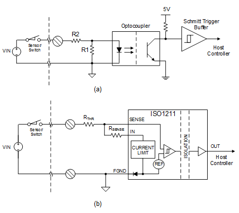
For many years, voltage detection applications have used optocouplers or photocouplers for isolation, as shown in Figure 1a. However, optocouplers provide only basic functionality and are limited by high propagation delays, a large current draw, poor reliability and an inability to operate at high ambient temperatures. Systems engineers have had to work around these limitations using external circuit components or by relaxing product specifications.
New isolated digital input solutions (See ISO1211, ISO1212) are now available that emulate the optocoupler in drawing power from the voltage being sensed, while also incorporating a high-voltage comparator and a precise current limit. Figure 1b shows such an approach. These solutions not only overcome the limitations of optocouplers, but also bring performance benefits in 9V-to-300V isolated voltage detection.

Digital isolators vs. isolated digital inputs
Digital isolators are popularly used as an alternative to optocouplers, in applications where they fit in the middle of the signal path. Examples include interfacing an ADC or a DAC to a microcontroller in an isolated analog input or output module, or isolating an RS-485 or CAN bus. Digital isolators have CMOS or TTL inputs and outputs, typically 5-V or 3.3-V. Isolated digital inputs are different from digital isolators in that they directly interface to the real world signals they are isolating. In doing so, they incorporate signal conditioning features such as a precise high voltage comparator, and an input current limit. They may also derive power from the signals they are measuring obviating the need for a “field-side” power supply.
Table 1 summarizes the performance benefits of optocouplers and isolated digital inputs in the context of isolated voltage detection.
| Feature | Optocouplers | Isolated digital inputs |
| No “field-side” power needed – powered by input signal | Yes | Yes |
| Failure in time (FIT) | 10-30 | 0.3 |
| Change in properties with aging | Yes | No |
| Maximum ambient temperature | 85˚C | 125˚C |
| Response time | 5µs | 150ns |
| Integrated current limit | No | Yes |
| Integrated comparator with Schmitt trigger | No | Yes |
Table 1: Comparison of optocoupler with isolated digital inputs
In this article, I’ll discuss a few voltage detection applications where isolated digital input solutions can bring distinct performance benefits over optocouplers.
110V, 220V and 240V DC and AC voltage detection
110VAC and 240VAC are popular line voltages for domestic and industrial use. 110V and 220V DC batteries are used as auxiliary power supplies in power distribution and power-station automation. Consequently, the detection of the absence or presence of these line and battery voltages, their exact levels, or the status of relays connected to them is an important function in a wide variety of applications, ranging from industrial automation to protection relays.
Traditionally, a circuit such the one shown in Figure 2 was used to detect an AC voltage. A full-bridge rectifier would rectify the AC voltage into DC. A Zener diode ensures that the optocoupler receives input current only beyond a certain voltage – this provides a crude threshold control. Resistors R1 and R2 provide additional voltage control while limiting the input current. The same circuit is used without the bridge rectifier for DC detection.

There are many limitations to this approach. First, the use of an optocoupler implies poor reliability, high propagation delay and thermal constraints. Second, the voltage threshold control is poor. The Zener diode ensures turn-on only beyond a certain voltage; after that, a certain current must be established before the optocoupler turns on. Due to variability in the optocoupler turn-on current from device to device, and with temperature, the voltage transition threshold also varies significantly. Third, the input voltage is usually subject to wide variation, as high as ±30% or more. If the component values are operating at the minimum allowed input voltage, with a weak optocoupler, the current draw at the maximum allowed input voltage with a strong optocoupler can be quite large. A high current draw results in high power consumption, leading to excessive circuit board temperatures.
Figure 3 presents a new approach to isolated voltage detection. In this approach, an adjustable current limit, a precise voltage comparator with hysteresis, reverse-polarity protection and galvanic isolation are combined in a complementary metal-oxide semiconductor (CMOS) semiconductor integrated circuit (IC). The power required for operation of the “field side” of the IC is derived from the field input; no separate field-side power supply is needed. The current limit is adjustable through an external RSENSE and the input voltage transition thresholds are adjustable by controlling the voltage drop across resistor RTHR. This approach results in tight control of voltage transition thresholds, as well as low power dissipation, since the input current is held constant by the in-built current limit.
Resistor RSHUNT helps extend the voltage range at the module input beyond the maximum voltage capability of the isolation IC. As the input voltage increases, the current through RSHUNT increases, increasing the voltage drop across RTHR and keeping the voltage at the IC input within allowed limits. For example, using this approach, an input voltage of 300VAC can be supported at the module input with a digital-isolation IC capable of only 60V.

Reducing power dissipation in multichannel applications
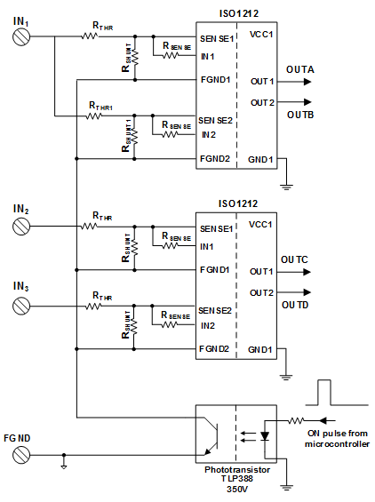
In multichannel applications, the current drawn from the input voltage can result in very high power consumption and dissipation, resulting in elevated board temperatures. A solution to this problem is to disconnect the ground connection to input detection circuitry, except for a short duration when the measurement is being performed. The fast response time of isolated digital inputs allows the isolated digital inputs to be switched on and off rapidly, with a low duty cycle, reducing the average current drawn from the high voltage inputs and drastically cutting down power dissipation. As shown in Figure 4, the ground connection of the isolated digital-input ICs can be duty-cycled with a phototransistor controlled by the host controller.
Figure 4 also shows the measurement of one input (IN1) with independent isolated digital-input channels to easily enable multilevel detection with different thresholds.

±48V detection in telecom power supplies
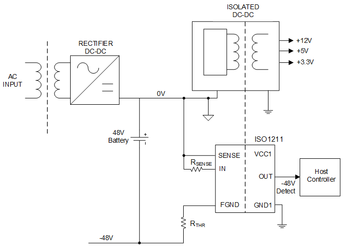
Telecom and wireless applications use 48V and -48V battery power supplies instead of 12V in order to reduce current draw for a given power level. This enables the use of smaller gauge wires while still being capable of carrying power over long wire runs with a minimum voltage drop as a percentage of the operational voltage. Isolated DC/DC converters convert the ±48V to lower voltages for microcontrollers and other lower-voltage ICs. An isolated digital input can indicate the presence or absence of the ±48V to the host controller, as shown in Figure 5. Adjusting resistor RTHR will obtain the exact threshold voltage needed.

Digital input modules in PLC, motor drives and building automation
In PLC, motor drives and building automation, digital input modules convert information from proximity sensors (inductive, ultrasonic, optical, etc.) or mechanical switches (door open or closed, excursion switch, etc.) into digital information that a controller or computer can process. 24V is the most common input voltage, though you can also use voltages in the range of 9V to 60V.
Digital input modules often have many channels, ranging from 8 to 256. In this case, the main advantage of an integrated solution, as shown in Figure 1b, is to keep the power consumption low. With optocoupler implementations, the power consumption keeps increasing with the input voltage, often resulting in unmanageable board temperatures. An isolated digital input solution with an integrated current limit can draw just the minimum current needed to bias the sensors or relays, and keep this current constant with increasing input voltage. You can reduce the power consumption by a factor of 2 to 5, significantly reducing board temperatures.
Conclusion
Isolated DC and AC voltage detection is ubiquitous in industrial applications, ranging from industrial automation to telecom and wireless communication to power distribution. Traditionally, optocoupler-based discrete circuits were used for voltage detection.
New isolated digital-input solutions that emulate an optocoupler response by drawing power from the voltage being sensed, while also incorporating a high-voltage comparator and precise current limit, not only overcome the performance limitations of optocouplers but also enable new capabilities.
References


Leave a Reply