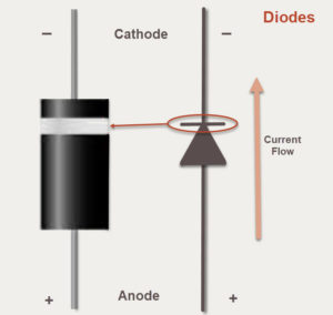
A diode is a passive component made with semiconductor materials (a chip) that conducts current flowing in one direction but does not conduct current flowing in the opposite direction. The symbol for a diode (to the right in Figure 1) looks something like an arrow pointing in the direction of the forward current. Current flows in one direction from the positive terminal (called the anode) to the negative terminal (called the cathode). An actual diode, shown to the left in Figure 1, is marked by a band on the cathode side. The band also corresponds to the symbol of the diode, indicating current flow.
The Current-Voltage curve of a diode (Figure 2) shows the response of the diode as a function of current versus voltage. An ideal diode would not conduct any current if reverse-biased (experiencing negative voltage), but would conduct current fully (as if it were just a wire) if we were to apply a positive voltage across the diode. From the IV curve, you can tell that a real diode is non-linear. Diodes are not indestructible. If you reverse-biased a diode past its breakdown voltage, the diode will conduct current in the wrong direction. Some diodes, called Zener diodes, are specially designed with a low breakdown voltage that can be safely exceeded without damaging it. A high voltage Zener diode, also known as an avalanche diode, is meant to operate beyond the breakdown voltage. A diode reaches avalanche breakdown when the reverse-bias voltage exceeds the breakdown voltage. Avalanche is more commonly known as a catastrophic phenomenon.
Speaking in terms of material science, avalanche concerns the reaction of electrons to the strength of the electric field at the PN junction of the semiconductor. Zener and avalanche diodes are different from regular diodes in that regular diodes are not designed to operate in reverse-bias mode. Thus, the I-V characteristics of Zener and avalanche diodes are meant to be used past the breakdown voltage.

When a diode is reverse-biased to the breakdown voltage, current flows in the wrong direction but the diode is not broken; it’s just not working as a one-way device anymore. However, it is possible to break any diode. The diode’s datasheet will show the maximum ratings, including the peak level of reverse-bias voltage that the diode can withstand. Many diodes can withstand very large voltages before reaching breakdown. Zener diodes are often used for circuit protection. Zeners are useful for protection against biasing a circuit over its rated voltage (e.g., in a crowbar circuit), regulating voltage in a circuit (a.k.a. Zener diode shunt regulator),
Another type of diode is the Schottky diode. Schottky diodes have a semiconductor metal junction whereas a standard silicon diode has a semiconductor junction. A metal-semiconductor junction has metal in contact with the semiconductor material. (One of the main differences is that the metal semiconductor current will be higher at the same voltage bias than a diode with a PN junction. Additionally, with a metal-semiconductor junction, modulation and switching can be much faster.) One of the results of the metal-semiconductor junction is that the Schottky diode has a much quicker recovery time coming out of a reverse bias state. Schottky diodes, therefore, are used where recovery time at higher frequencies matter. Schottky diodes are used to clamp voltages (i.e., move the complete signal up or down in voltage level without changing the signal), for reverse current and discharge protection, and in switched mode power supplies.
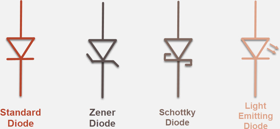
One diode that many people use every day is the Light Emitting Diode (LED). Technically, diodes are passive devices because like resistors, capacitors, inductors, and transformers, they do not control a signal (or current) using an electrical signal, even though it’s difficult to see them as passive when the LED releases visible energy as light. Nevertheless, the LED is another type of semiconductor-based diode that also conducts electricity when forward biased. The polarity of LEDs means that they will not shed light when the voltage is reverse-biased. LEDs used for indicators in circuits will have one longer leg that is the anode (+) and the shorter leg is the cathode (-).



Nice diagrams but I think there may be an error in the text.
The coloured band is at the cathode end of the diode as shown in the diagram, not the anode as stated in the text. In a rectifier, the (conventional) current flows out of the cathode, which makes it appear to be the positive terminal, but in fact it is at a slightly lower potential than the anode when the diode is conducting.
Historically the diode was developed in a vacuum tube. The cathode emitted the cloud of electrons, which traveled from the cathode to the plate. This determined the direction of current flow.
You have everything correct except the direction of the current flow. It’s
backwards. So when explaining
how a diode works current is going the wrong way.