(editor’s note: Intrigued by these power electronics problems? Have a question or another solution? Then click the “Read more” link and follow the conversation on EDAboard.com or log in to EDAboard and participate in the power electronics forum threads.)
Power MOSFET forensics – I need your help to investigate a recent MOSFET death. It was one of the four paralleled MOSFETs of an H-bridge high-side switch (sine wave inverter). The MOSFET was rated at 130A (thus the paralleled group was rated at 520A), the load current was lower than 50A, and I had an inline fuse (automotive type) of 90A (three 30A ones in parallel).It seems like the Mosfet died short then the fuse has blown. Anyway, there was no smell & smoke (there was absolutely no visible sign of damage). Could anyone explain the cause of death? Read more
PC power supply short circuit – My PC power supply just failed couple days ago and I didn’t know that until I asked people that my PC just stopped running, I thought it might be the CPU but they told me it’s probably the PSU. So I opened the PSU and checked the rails and found that the 12V rail is short-circuited with the ground. Read more
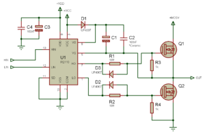
Diode Resistance in MOSFET bridge – In an IGBT/MOSFET H-bridge for AC drive or inverter power circuit, generally 1N4148 diodes are connected to gate terminals for adjusting the turn-off time. How do you calculate the diode resistance in this case? Read more
H-bridge for single-phase AC motor drive – I am working on single-phase ac motor drive project. The schematic is attached only for H-bridge. I have generated SPWM signals using an opamp. When I connect resistive load I get the AC output voltage as expected. But when I connect 150 W AC motor of a washing machine, the motor rotates for few seconds and then my input fuse blows. While testing, I give SPWM signals to the H-bridge first, then slowly apply the AC input voltage through variac. Read more
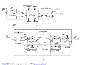
Designing power supply with low output power – I have a project where I need to design a power supply that is connected to the grid (230Vrms, 50Hz) and has two output voltages. The grid’s voltage isn’t rigid and varies between 140-250Vrms. My power supply should have 2 outputs with galvanic isolation:
– Output #1 supplies 24Vdc +-5% with a maximum current of 150mA.
– Output #2 supplies 5Vdc +-2% with a maximum current of 100mA.
Linear regulators aren’t an option because of its low efficiency and the huge amount of heat it needs to dissipate. So switched mode power supplies are our only option. What do you think is the best design to come up with? Two buck converters with a 50Hz transformer on input? Flyback converter? Read more
Zero-load switching losses – I’m bringing up a new full bridge ZVS converter (400 Vin). The first thing I did was run the primary bridge with zero load – the xfmr was de-populated thus both switched legs of the first full bridge went nowhere. I expected to see low losses, verify that the circuit could handle full Vin and move on but I immediately saw losses steeply increase as I applied input voltage. Using 650V fets in 8x8mm SMT packages ‘high losses’ means something like 1-3W here. First I assumed it was shoot-through but I quickly ruled that out (digital control meant I could easily adjust dead-time). Ok so help me understand the variables here because it’s not adding up? Read more
Using 6 thyristors as SSR in 3-phase – I am using six thyristors as a switch in 3-phase like below:
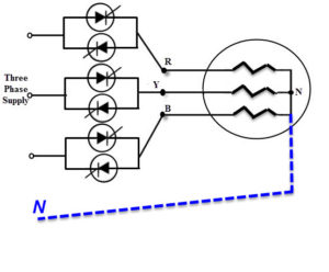
I trigger each thyristor on zero time in its phase. (I use zero crossing).
It works when neutral is connected on star center but it doesn’t work when the neutral wire is disconnected.
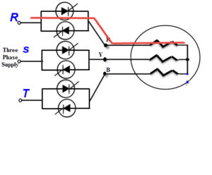
What is the problem? I think when the thyristor’s R phase is triggered because other thyristors are off it can’t turn on (like below):
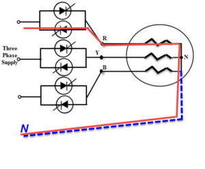
But when the neutral is connected there is a way to flow current in load like below:
How must I trigger thyristors that work in the circuit without a neutral wire? Read more
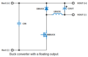
Buck with FET in the low side – The attached buck converter uses the MOSFET in the low side, however, the drawback is the floating output. This makes it easy to drive the MOSFET and even can be used as buck converter for input voltage as high as rectified mains because no high voltage capacitor is needed for the bootstrap.
1) Why isn’t this topology as popular as the usual one? Only because of the floating output? Is there any issue I do not see?
2) I do not see any problem in changing the output filter inductor at the cathode of the diode. Am I right? Read more
Buck converter, damaged circuit – I use an IGBT (VCE>800 , IC=35) instead of BJT transistor with a IGBT driver (VCC=15v). I want to get a 1A current output with switching frequency 50 kHz (duty cycle less than 15%). However, after I inject 220VAC as input, my IGBT is gone and after that my circuit behind the gate, such as IGBT driver, and the PWM generator are gone, too.
What is my mistake? Read more


Leave a Reply