Isolation from the AC line is essential for user safety in many situations and can be implemented using a special isolation transformer as well as other means.
“Isolation” is one of those terms which gets tossed around and is often cited as an almost universal, all-purpose cure for various ongoing or possible circuit and system problems – and it often is. However, as with most topics, there’s more to isolation than its definition. This FAQ discusses what AC-line isolation is, why it is needed, and how it is achieved.
Q: What is meant by isolation in circuits?
A: In the electronics sense, isolation means there is no “ohmic” or “galvanic” path between two conductors, subcircuits, or subsystems. In basic terms, if you connect an ohmmeter between points A and B, the reading will be near-infinite ohms.
Q: Why is isolation needed?
A: There are two primary reasons for needing isolation: 1) functional signal isolation, to ensure the overall circuit and system works properly during normal operation; and 2) safety isolation, to ensure no danger to a user in case of occurrence of certain fault modes. These two aspects sometimes overlap but often do not. There are many solutions to signal isolation, but many of these do not apply to safety isolation. We’ll be looking only at the safety/failure perspective here.
Q: What is the objective of AC-line isolation?
A: It is needed to prevent the undesired flow of current through a user, who can be someone operating an instrument or someone connected to it, such as in a medical situation.
Q: Would this current flow occur during normal operation?
A: No, it is strictly a fault-mode situation where isolation prevents a dangerous situation in the form of electrical shock in the event of certain types of faults and fault scenarios.
Q: What does isolation do in these cases?
A: The answer starts with reviewing the first principles of electric-current flow and the paths this current flow takes. The user is at risk if current, driven by the AC line’s potential, flows through the user’s body and back to its source. However, if that currently has no return-flow path through the body, then there is no risk even if the person is touching a high-voltage line.
Q: I thought “grounding” and “ground” were supposed to remove AC-line shock risk?
A: Ground is part of the solution and can be part of the problem when a fault occurs. First, let’s be clear what we mean by “ground,” the most misapplied and misused word in electronics.
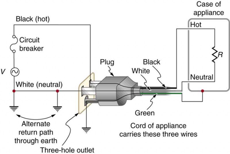
Start with AC-line basics: A single-phase AC line has three wires: line (L), neutral (N), and ground, where ground is a true Earth connection and normally carries no current, Figure 1. In standard house wiring, the ground wire (green) is often not insulated and left as bare exposed copper. Many do-it-yourself folks unknowingly swap the hot and neutral wires or have a broken ground connection – and things still work fine, that is, until a fault occurs. (Why some items like decorative table lamps have two-wire plugs and do not need three-wire plugs – and that’s actually safe and OK – is explained later).
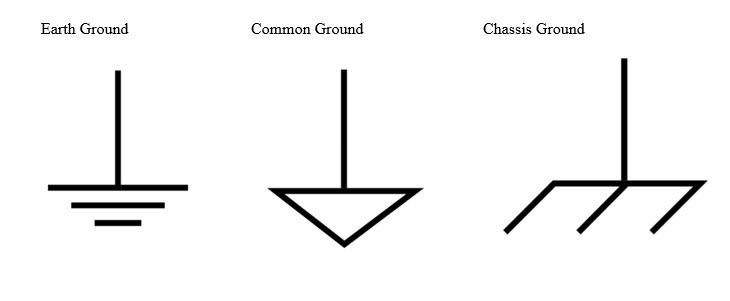
Note that “Earth ground” is not the same as “chassis ground” or “common” (signal ground), and there is a different symbol for each (Figure 2), although the word “ground” is often causally used for all three. In fact, a battery-operated device such as a smartphone or even an airplane have no Earth ground.
Q: So why is line isolation needed, and how is it accomplished?
A: Consider a standard line-operated product, which can be an appliance or a medical instrument, usually but not always using a transformer with a primary side and a secondary side, often at lower voltage via the step-down turns ratio. There is no galvanic path between the two sides, so the operating circuit is electrically isolated from the AC line.
Q: So what’s the problem?
A: Assume there’s an internal power-line short circuit (such as from insulation rubbing and fraying) and the instrument case becomes “live,” thus putting the user at risk. The excess current will flow to the case, which is connected to Earth ground via the third wire of the AC connection. Now, the dangerous current will flow through the case and then to ground, and the operator will be safe.
Q: That sounds safe, so what is there to worry about?
A: The reality is that the AC ground is not always there as intended or assumed. The AC cord and plug or, more likely, the socket was misfired and may lack a real connection to Earth ground (this often happens due to sloppy initial work, poorly done “upgrades”, corrosion, and other factors). Then, the fault current seeks another low-impedance path to return to ground, but this time through the user and his/her body, and often through shoes and floor or perhaps a water pipe he/she is holding, (Figure 3).
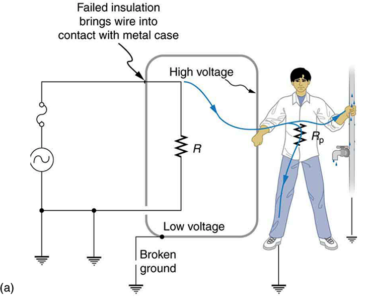
This resistance path is not necessarily a path of a few ohms; it may be on the order of kilohms. But it still provides a path and circuit for the current flow from fault, through user, to local ground, and then to Earth ground. Keep in mind that the absence of that true ground connection is not noticed when things are working.
It’s the current that kills
Q: I’m getting confused here with the interaction between current and voltage. One moment, we are worried about high voltage, then we are worried about current flow. What’s going on?
A: People normally associate shock risk with higher voltages. This is a valid correlation but only in an indirect way. What causes shock – whether at or below a lethal level – is current flow through the body. In turn, this current flow is due to a voltage that drives (forces) the current into and through the body. This relationship is made clear by the term “electromotive force” (EMF), very commonly used for voltage in earlier days (and still used in some cases).
Q: Can you explain further?
A: In any discussion about voltage and current and dangers, it’s easy to forget some basics:
- Voltage is not defined as a single point; it is defined and measured between two specific points. A better name for voltage is “potential difference.”
- This potential difference causes current to flow, and the amount of current depends on the resistance between the two points and that potential difference, as characterized by Ohm’s Law. The larger this potential difference, the greater the current flow and the greater the risk it poses.
Q: How much current is dangerous?
A: This question has multiple answers, depending on where the current is applied to the body and what detrimental effect is being considered. A standard line voltage (110/230 V; 50 or 60 Hz) across the chest even for a fraction of a second can induce ventricular fibrillation at currents as low as 30 mA (note that danger levels for DC are much higher at around 500 mA, but we are discussing AC). If the current has a direct pathway to the heart, such as via a cardiac catheter or other kinds of electrode, a much-lower current of less than 1 mA can cause fibrillation.
Q: Can you be more specific about the danger of current?
A: These are some standard thresholds which are often cited for current through the body via skin contact:
- 1 mA: Barely perceptible.
- 16 mA: Maximum current an average-size person can grasp and “let go.”
- 20 mA: Paralysis of respiratory muscles.
- 100 mA: Ventricular fibrillation threshold.
- 2 A: Cardiac standstill and internal organ damage.
The levels are also a function of the current-flow path, meaning where the two points of contact with the body are located, such as across or through the chest, from an arm down to the feet, or across the head.
Q: So, it’s voltage driving current that’s the danger, as long as there is sufficient current at the source to be driven?
A: Yes. As further “proof” that it’s the current that kills, think of a common spark of static electricity. The voltage there is typically 10 to 20 kV per inch of spark (depending on humidity and dust in the air), and it’s quite common to create a spark of several kilovolts or more when walking on a carpet, for example, on a dry day. Yet that high-voltage spark does not hurt because of the available current in the safe femtoamp (fA) range.
The next part of the article discusses what can be done to ensure isolation and thus safety in case of the double fault.
Related EE World content
High-isolation 3-W dc/dc converters optimized for medical, industrial apps
Power transformers feature high clearance/creepage distance isolation
Low-power transformers meet isolation, creepage, clearance safety standards
2-kW modular supplies with full MoPPs Isolation feature low acoustic noise, up to 18 outputs
Isolation technology helping solar power connect to grid
550-to-650-W modular supplies sport full MoPPs isolation, low acoustic noise, up to 10 outputs
Galvanic isolation for electric vehicle systems
External References
- Autodesk, “How does ground work in electronics?”
- Analog Devices, “Isolation in Digital Power Supply—Why and How”
- Associated Research, “Use of an Isolation Transformer While Performing Leakage Current or Functional Run Tests”
- EtechoG, “Applications, Advantages, Disadvantages of Isolation Transformer”
- Lumen Learning, “Electrical Safety: Systems and Devices”
- Voltech Instruments, Inc., “InterWinding Capacitance”
- OpenStax CNX (Rice University), “Electrical Safety: Systems and Devices”




Leave a Reply