Power-on glitches and system malfunctions are a special challenge as rail voltages drop, but the right ICs eliminate the problem.
Experienced engineers know that one of the riskiest times for a system is when power is applied. Depending on time constants and how smoothly and quickly the power rail comes up to nominal, the different ICs and parts of the system may start, lock up, or start in an incorrect mode as they attempt to work with each other. Adding to the challenge is that the timing and slew-related performance of the ICs on power-up can be a function of temperature, associated capacitors, mechanical stress, aging, and other factors.
The potential problem is aggravated as operating-voltage rails drop to low single-digit values, reducing the amount of “slack” or headroom for functioning with the nominal rail value. All of these factors can lead to inconsistent startup performance and frustrating debug sessions.
For these reasons, analog IC vendors have devised specialized ICs that offer supervisory management features that eliminate the uncertainty and inconsistency of power-up. This article will define and characterize the glitch problem and then show how it can be avoided through the addition of some small, specialized ICs.
Start with glitch definitions
As with many engineering terms such as “buffer” or “programmable,” the word “glitch” has different meanings depending on context. A glitch can be due to one of many circuit “apparitions”:
- a noise-induced spike on a signal or power line.
- a sudden, brief drop in a power-supply rail due to a load transient.
- a microsecond period when both upper and lower MOSFETs in a bridge are inadvertently turned on simultaneously as a result of different turn on/off times in their gate drivers (a very bad occurrence).
- or a momentary indeterminate signal and associated race conditions due to timing tolerances and differences between components.
Here, we look at one type of glitch that can occur during the “power-up” period when power is turned on and the ICs are transitioning to their normal operating condition, especially in lower-voltage systems. Such power-on glitches are especially frustrating because they can cause intermittent, inconsistent, hard-to-debug problems that have no apparent correlation or consistency.
As the glitch-inducing conditions are often “on the edge” of happening, their occurrence can vary with temperature, power-rail tolerance (while still within specification), individual component variations in a batch of the same devices, and other hard-to-determine factors.
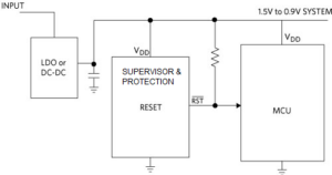
What is this glitch, and what is its source? Consider a system with a microcontroller and an associated supervisory/protection reset IC. The role of the latter IC is simple and focused: to maintain reliable system operation during power-up, power-down, and brownout conditions (Figure 1).

In a typical battery-powered application, the DC-DC converter generates the supply rail from a small, low-voltage battery. This supervisor IC is generally added between the DC-DC converter and the microcontroller to monitor the supply voltage and enable or disable the microcontroller.
The reset IC ensures reliable operation by accurately monitoring the system power supply and then asserting or de-asserting the microcontroller’s reset input. Doing so guarantees that the voltage level is above the microcontroller’s minimum operating voltage. The IC also ensures there is an adequate amount of time for the power supply to settle to its nominal value.
How does the glitch happen? The enabling and disabling of the microcontroller is managed via the supervisor IC’s reset output pin. This pin is typically an open-drain pin that is connected to a 10-kΩ pullup resistor. The supervisor IC monitors the power supply voltage and asserts a reset when the input voltage falls below the reset threshold.
After the monitored voltage rises above the threshold voltage, the reset output remains asserted for the reset timeout period and then de-asserts. This allows the target microcontroller to leave the reset state and begin operating.
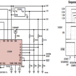
But what happens to the reset output before the supervisor turns on and pulls the reset output low? The answer is found by looking closely at a typical power-up sequence (Figure 2). As supply-rail Vcc begins to power up, both the microcontroller and the supervisor are off as they should be. As a consequence, the reset line is floating, and the 10-kΩ pullup resistor causes the voltage to track Vcc.

This voltage rise can be anywhere between 0.5 V to 0.9 V, potentially causing system instability. Once the supervisor IC turns on, the reset line is pulled down to prevent the microcontroller from inadvertently turning on. This glitch is common to all previous generations of supervisor ICs.
The second and final part of this article examines why this glitch problem is potentially more severe as system rail voltages drop to the low single digits.
EE World Related Content
Catch that glitch: Finding race conditions
Glitch-free power supervisor IC protects low-voltage IoT apps
Smart fuses optimized for sub-power rails in server apps
External reference
Analog Devices/Maxim Integrated Products, Design Solution 7550, “Is Your Application Protected from Glitches?”


Leave a Reply