How a motor ramps its angular position or rotational velocity from a starting point to the intended target value is a complicated topic which modern motor controllers address in many ways.
Part 1 was an introduction to issues related to motor and motion control. This part will focus on the topic of motor ramping and trajectory options. How to direct the motor and its load to go from their initial position or velocity from a starting point to the target goal while also managing acceleration and precision is a complicated, multifaceted topic.
However, there are a few basic and well-known approaches which are widely used due to their simplicity and relative effectiveness: the trapezoidal and the S-curve. We can look at them in the context of a point-to-point move, where the load is accelerated from a stop to a constant velocity, and then decelerated such that the final acceleration, and velocity, are zero at the moment the load arrives at the programmed destination.
The obvious way to do this is via a trapezoidal profile which has just three 3 phases: constant acceleration, constant velocity, and constant deceleration. The trapezoidal profile has instantaneous transitions between these phases (Figure 1). In a trapezoidal profile, the jerk (rate of change in acceleration) is infinite at the phase transitions (in theory only but not in reality, of course). This profile has the virtue of getting from start to finish in the least time.
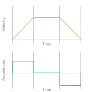
In many cases, the jerk at the beginning and end is unacceptable. Not only can it cause disruption or breakage at the load, it is often physically hard on the motor assembly itself. Finally, it may initiate resonance of the motor and load, and any such resonance mean the motor/load positioning will be less accurate and can even become difficult to manage or control, as resonances often tend to develop a “life” of their own.
An alternative to the trapezoid is the S-curve, which is a superset of the trapezoidal profile (Figure 2). The S-curve motion profile has seven phases. In Phase I, the load moving from rest at a linearly increasing acceleration until it reaches the maximum acceleration. In Phase II, the profile accelerates at its maximum acceleration rate until it starts decreasing as it approaches the maximum velocity. (This occurs in Phase III when the acceleration linearly decreases until it reaches zero.) In Phase IV, the control velocity is constant until deceleration begins, then decelerates in a profile which is symmetrical to Phases I, II and III.
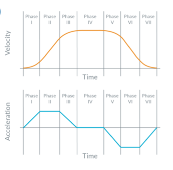
Note that the simpler trapezoidal profile only has three phases of the S-curve profile: #2 (constant acceleration), #4 (constant velocity), and #6 (constant deceleration).
In addition to these basic ramping profiles, many vendors offer proprietary enhancements or “twists” which are intended to improve one or more aspects of performance. For example – and this is just one of the many available ones – Trinamic Motion Control GmbH & Co. KG (now part of Maxim Integrated Products, Inc.) offers their SixPoint™ profile which adds a user-configurable start/stop frequency and waiting period (Figure 3). Adding this to the linear-motion profile ensures that all oscillations are gone from the mechanical system, which they maintain supports faster positioning as it eliminates the resonances caused by trapezoidal ramping.
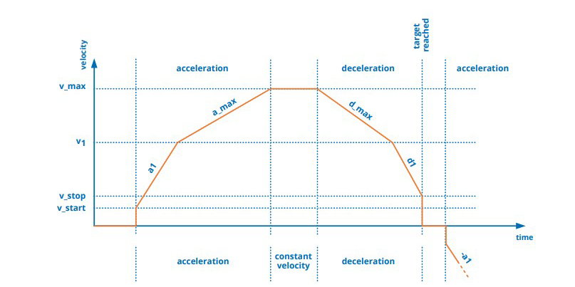
Trinamic says that this velocity ramping profile also adds a reduced acceleration value at high velocity which reduces jerking at the end of standard acceleration ramps. This ramping profile allows for faster positioning through additional acceleration segments but without the undesired consequences.
Of course, it’s one thing to sketch out a desired profile “on paper” but it’s another to make it happen in reality. System inertia, resonances, and other factors greatly complicate the situation and must be taken into account, and there are added complexities of friction, flexing, backlash, and slack. Determining the curvature of the “S” part of the profile (if that is the one used) is just one of the issues the designer must resolve.
For closed-loop systems, the loop parameters must be “tuned” to the loop and load dynamics, and doing so range from fairly simple to very difficult depending on the nature and constancy of the load. Modeling the control system and loop and simulating its performance involves many advanced equations or specialized application packages (such as from The MathWorks or ComSol) which have facilities for greatly simplifying the task.
Part 3 of this article will look at some available motion-control products from different types of vendors and at various levels of integration.
EE World Related Content
Basics of AC, DC, and EC electric motors, Part 1— AC and DC
Basics of AC, DC, and EC electric motors (Part 2) — EC and stepper
What is Proportional (PID) Control and why is it used? (Part 1)
Motor field-oriented control, Part 1: Principles
Motor field-oriented control, Part 2: Implementation
Motion control ICs handle advanced velocity control of servomotors
Motor controller includes three-phase gate driver and voltage regulator
References
Performance Motion Devices, “Servo Motor Tuning – Rocket Science or Walk In the Park?”
Performance Motion Devices, “New Control Technique Combines Servo Performance With Step Motor Cost”
Performance Motion Devices, “Mathematics of Motion Control Profiles”
Performance Motion Devices, “S-Curve Motion Profiles – Vital For Optimizing Machine Performance”
Performance Motion Devices, “Juno Family of Velocity & Torque Control ICs”
Trinamic Motion Control, “Motion Control Technology”
Trinamic Motion Control, “TMCM-1321 servo controller/driver module”
Texas Instruments, Application Note SPRABQ7A, “Sensorless Trapezoidal Control of BLDC Motors (Rev. A)”
Texas Instruments, Application Note SLYT568, “Closed-loop motor control: An introduction to rotary resolvers and encoders”
Texas Instruments, Application Note SPRABZ3, “Sensorless Trapezoidal Control of BLDC Motors”
Texas Instruments, “TIDA-00143 BLDC Motor Controller Reference Design”


Leave a Reply