The optocoupler — also called an optoisolator — is among the most useful, versatile, problem-solving components available to the design engineer. This small non-monolithic device does one thing and does it well, with minimal complications in most cases and no software.
This FAQ will look at the operation principles, key parameters, and applications of this widely used component.
Q: In simplest terms, what is an optocoupler?
A: It is an electro-optical component (usually with just four terminals) and a conceptually simple operating principle, Figure 1. Two of the terminals connect to and drive, an infrared (IR) LED, while the other two are the output of a phototransistor (housed in the same package) which senses the light given off by the LED. (A special optical conduit is built into the optocoupler between the light emitting LED and the phototransistor receiver).
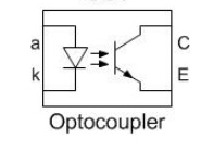
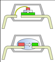
Thus, the coupling between the input LED and output phototransistor is optical, not electrical. The LED can be positioned above the phototransistor or adjacent to it, Figure 2. The package is typically just a few mm on each side, somewhat like a 4-pin DIP IC.
Q: Then what happens?
A: As more current is pumped into the LED, the LED’s output increases. When the current is zero or close to it, the LED is producing no or few photons. Thus the phototransistor is “off” and no current (except for a little leakage current) flows from its collector to emitter. As the LED current increases, the phototransistor conducts more current, until it is fully on (saturated) and it conducts maximum current with only a small voltage drop across its output.
Q: What is the consequence of this coupling using an optical path?
A: The result is that there is no galvanic (ohmic) path between input and output. The information carried by the input-side electrical signal becomes an output-side electrical signal, but without any interposed electrical path.
Q: Why is this needed?
A: There are many situations where two parts of a system or circuit must be electrically isolated. Among the many situations are these:
—one side of the circuit s grounded, but the other side is not (“floating”), as when driving the upper MOSFET in an H-bridge drive topology;
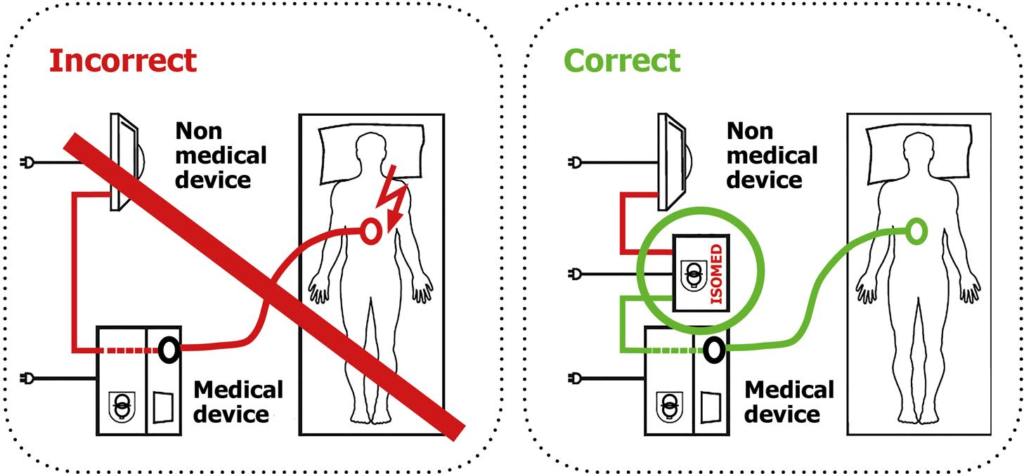
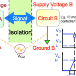
—when safety and possible failure modes dictate that a high-voltage circuit and a lower-voltage one must be separated, for user and system as well as electrical interface issues, Figure 3;
—even in low-voltage circuits such as cars, they ensure that a failure in one circuit function does not “ripple” into other others and cause additional failures;
—when a system must measure the voltage across an individual battery in a series-connected string of batteries;
—when subcircuits have different ground potential;
—when there is a common-code voltage or noise between two subcircuits which must be negated or canceled so only the desired differential signal remains;
—where a power regulator must have primary side-secondary side isolation (provided by a power transformer) but the primary side also needs feedback from the output to control the regulation function, and this feedback signal must be isolated to maintain overall regulator isolation;
These are just a few of the many situations which either benefit from — or mandate — electrical isolation. Part 2 of this FAQ will look at some in more detail.
Q: Are there alternatives to the optocoupler?
A: Yes, there are other techniques for achieving galvanic isolation: magnetic using transformers or coupled coils (can be used for DC and low-frequency by modulating of a higher-frequency carrier), capacitive using IC-fabricated parallel places, and even RF. Each has virtues and drawbacks (not discussed here), but the optical-based solution is among the most widely used.
Q: Can optoisolator be used for analog and digital signals?
A: Yes, absolutely. Some are optimized for digital (on/off) signals, where the input of the phototransistor is used to fully allow or block current flow. In this situation, the optocoupler is used as a solid-state relay to replace an electromechanical relay. In other cases, such as the feedback signal of a power regulator, the optocoupler is operated in an analog mode, and the output is fairly linear with respect to the input.
Q: What are some of the possible drawback to the optocoupler?
A: First, it is an active device and the LED must be driven with the suitable amount of current, which can range from 20 mA to about 50 mA. Also, there is a phenomenon called LED aging in which the LED output degrades over time, and typically reaches half-power after about 20 years. This means the working lifetime of the optocoupler may be less than the application can tolerate. However, improvements in process technology have reduced this aging significantly, and some vendors guarantee their devices will meet specifications for 20 years.
Q: Is that all?
A: No, there’s more, especially as an SSR replacing the electromechanical relay. An optocoupler must have current flow in its output, and it cannot provide what is called a simple “dry circuit” contact-closure which an electromechanical relay offers. Further, the electromechanical relay supports a wide range of input types and ranges (current and voltage) for both the coil and the contacts, and there do not have to be similar; for example. A relay can use a 5V DC signal to control a 120V AC line directly.
Also, unlike electromechanical relays, optocouplers are single-input, single-output, normally open SSRs, (although there are some specialized ones with multiple parallel outputs via dual phototransistors. No SSR can emulate a single electromechanical relay with multiple, simultaneous normally open and normally closed contacts. Finally, relay contacts can be sized to directly switch high voltages and currents, while an optocoupler’s capability is far more limited – but this is not a problem in many applications.
Part 2 of this FAQ will look at parameters and applications in more detail.
References
- EEWorldonline.com, Power Electronic Tips, “Solenoids and relays, Part 1”
- EEWorldonline.com, Power Electronic Tips, “Solenoids and relays, Part 2”
- EEWorldonline.com “Galvanic isolation for electric vehicle systems”
- EEWorldonline.com, “Electrical isolation technology at Silicon Labs”
- EEWorldonline.com, “Why isolated digital inputs are replacing optocouplers in up to 300V systems”
- EEWorldonline.com, “Selecting an optocoupler to isolate a PWM”
- EEWorldonline.com, “How should grounds and commons be connected to each other?”
- EEWorldonline.com, “Flashovers and clearance in electronic equipment”
- Renesas Electronics Corp., “Current Transfer Ratio (CTR) and Response Time of Photocouplers/Optocouplers”
- Fairchild/ON Semiconductor, Application Note AN-3001, “Optocoupler Input Drive Circuits”
- Vishay Semiconductors, Application Note 01, “Guidelines for Reading an Optocoupler Datasheet”
- Vishay Semiconductors, Application Note 02, “Optocouplers and Solid-State Relays: Application Examples”
- California Eastern Laboratories, “Application Based Optocoupler Design Guide”
- California Eastern Laboratories, “Optocouplers Product Selection Guide”
- Kynix Semiconductor Electronic Blog, “How Optocoupler Works and the Optocoupler Basics”
- Elprocus, “Opto Couplers – Types & Applications”



That’s an excellent post. Thank you! It had not dawned on me that the optocoupler cannot be a “dry switch”, but now that I have read this it so obvious that it can’t! You saved me days of frustration. 🙂