Digital isolators have two primary functions, to provide isolation and to transmit information across the isolation barrier. Part one looked at the various specifications related to voltage and isolation performance. Part two details key specifications related to the transmission of information.
Common‐mode transient immunity (CMTI) is one of three key specifications of digital isolators. The other two key specifications, isolation rating and working voltage, were discussed in part 1 of this series. CMTI is the ability of an isolator to handle high slew rate voltage transients between its two grounds without corruption of the signal. Too low a CMTI can lead to bit errors in the transmission. High CMTI indicates a robust isolation channel.
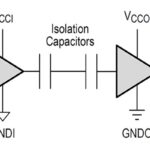
CMTI testing is done for positive and negative transients with the inputs of the device being tested tied to HIGH and LOW. Two common digital isolator technologies are an air core transformer, or coupled inductor, and silicon dioxide capacitors. A commonly used CMH test criterion is the maximum sustainable common-mode voltage slew rate while keeping Vout at greater than 80% of VDD2. For CML, the requirement is to keep VOUT under 0.8 V. As shown in Table 1, transformer-based isolation outperforms capacitive designs.

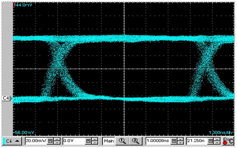
The importance of a high CMTI is evident in the performance of a digital isolator that features a minimum 100kV/μs CMTI and can support a data rate of 150 Mbps. In Figure 1, the oscilloscope was set to 1.0 ns/div. The eye pattern demonstrates that data integrity was maintained with a 2 ns pulse width distortion and 350 ps peak jitter.
The following is a selection of additional digital isolator specifications related to data transmission, including propagation delay, channel matching, and output enable and disable times:
- Pulse width (PW) is the minimum pulse width needed for normal operation.
- Propagation delay time (H to L), tPHL is the time needed for the output to change from high to low after the input signal changes.
- Propagation delay time (L to H), tPLH is the time needed for the output to change from low to high after the input signal changes.
- Pulse width distortion (PWD) is the absolute difference between tPHL and tPLH in a channel.
- Propagation delay skew, tPSK is the dispersion in propagation delay times between different isolators.
- Channel matching:
- tskSD is the difference in propagation delay time between channels in the same direction.
- tskOD is the difference in propagation delay time between channels in the opposite direction.
- Output enable time:
- tpZL is the time it takes for the output to change from high impedance (Z) to low-level after a change in the control signal.
- tpZH is the time it takes for the output to change from Z to high-level after a change in the control signal.
- Output disable time:
- tpLZ is the time it takes for the output to change from low-level to Z after a change in the control signal.
- tpHZ is the time it takes for the output to change from high-level to Z after a change in the control signal.
Summary
The three key specifications for digital isolators include isolation rating, working voltage, and CMTI. The first two were reviewed in part 1 of this FAQ series. CMTI and other specifications related to information transmission were detailed above. CMTI is an especially important spec and is strongly correlated with data transmission speeds. It differs for transformer-based and capacitive-based isolators.
References
Common-Mode Transient Immunity, Analog Devices
Digital Isolator EMC Application Notes, Toshiba
Digital Isolator Design Guide, Texas Instruments


Leave a Reply