Power supply control has evolved from primitive ferroresonant regulation and linear power supplies to simple hysteretic control, analog voltage-mode control, analog current-mode control, and now various approaches to digital control. Compared with switched-mode power supplies, the output of ferroresonant designs is not as precisely regulated, while linear regulation can produce very tightly regulated and very low noise outputs. Ferroresonant and linear power supplies are much simpler but are less efficient than switched-mode designs. The various switched-mode control techniques in most electronic systems provide the best combination of high efficiency and output regulation.
Ferroresonant control is a transformer-based technique that uses nonlinear magnetic properties and a resonant circuit to provide a stable output voltage over input voltage variations as large as ±40%. Ferroresonant power supplies are environmentally rugged, inherently current limiting, and absorb most power line induced transients. Before the spread of switched-mode technology, ferroresonant power supplies were the primary source of -48Vdc power in every telecommunication central office.
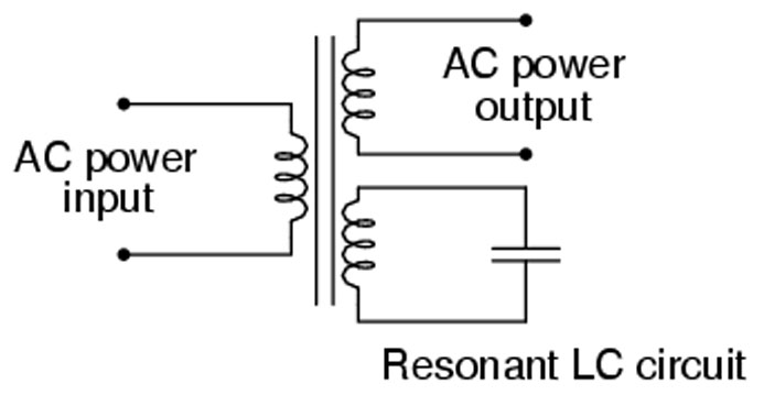
A ferroresonant transformer consists of an auxiliary secondary winding with a parallel capacitive tank to provide a resonant circuit at the supply voltage frequency (Figure 1). Regulation results from the saturation characteristics of the transformer’s iron core together with a resonant LC circuit on the same core. The resonant circuit can sustain the output voltage for several milliseconds if the AC input varies or drops out. The resonant circuit also acts as a filter to reject harmonics produced by the core saturation.
Linear regulators
Like ferroresonant designs, linear regulators (linears) are an inefficient dissipative technology. A basic linear consists of a pass transistor used to regulate the output voltage (Figure 2). Control is provided using feedback from a resistor divider that senses the output voltage. The feedback voltage is compared with a reference voltage in an error amplifier. The output of the error amplifier controls the pass transistor. The error amplifier constantly adjusts its output voltage (and the current through the pass transistor) to force the feedback voltage equal to the reference voltage.
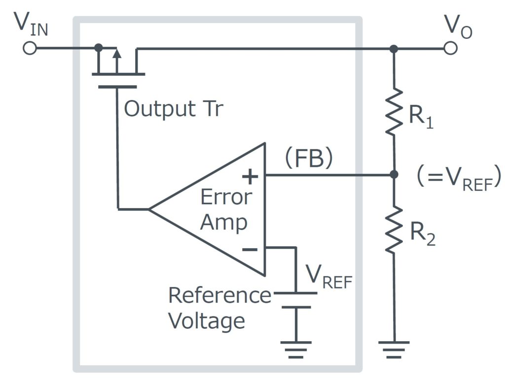
The dropout voltage is an important specification for linears. The minimum voltage drop is required across the regulator to maintain output voltage regulation. There are three basic types of linear regulator designs:
- Standard linear (NPN Darlington driven by a PNP transistor), drop out voltage up to 3V
- Low Dropout (LDO) linear, drop out voltage 1V to 2V with an NPN output transistor, 0.7V or less with a PNP or MOSFET output transistor
- Quasi LDO with a drop out voltage 0.9V to 1.5 V
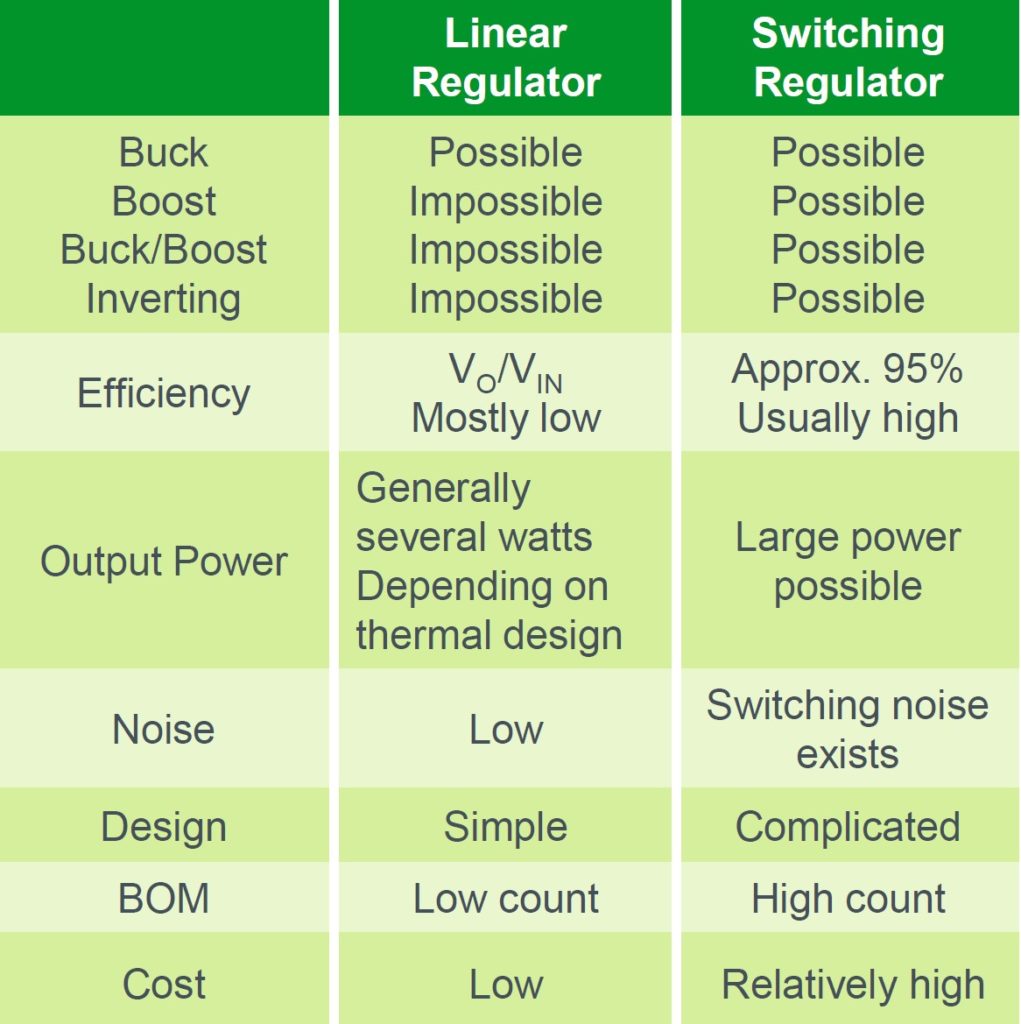
Standard linears are best for AC-powered applications, where low cost and relatively high load current are required. LDOs are best suited for battery-powered applications because the lower dropout voltage translates directly into cost savings and longer battery life. Regardless of the drop-out voltage, all linears are buck regulators (Table 1). Switched-mode control is required to implement boost, buck/boost, or inverting power conversion.
Three flavors of switch-mode control
The three main switched-mode analog control topologies are hysteretic, voltage, and current. Each provides unique performance tradeoffs. Hysteretic control (also called bang/bang control) is the simplest implementation and needs no compensation to maintain stability. The output voltage is sensed and compared with a reference in a hysteretic controller. A switching cycle is started when the output voltage reaches a lower threshold and is terminated after a constant time period or when the output voltage reaches an upper threshold (Figure 3).
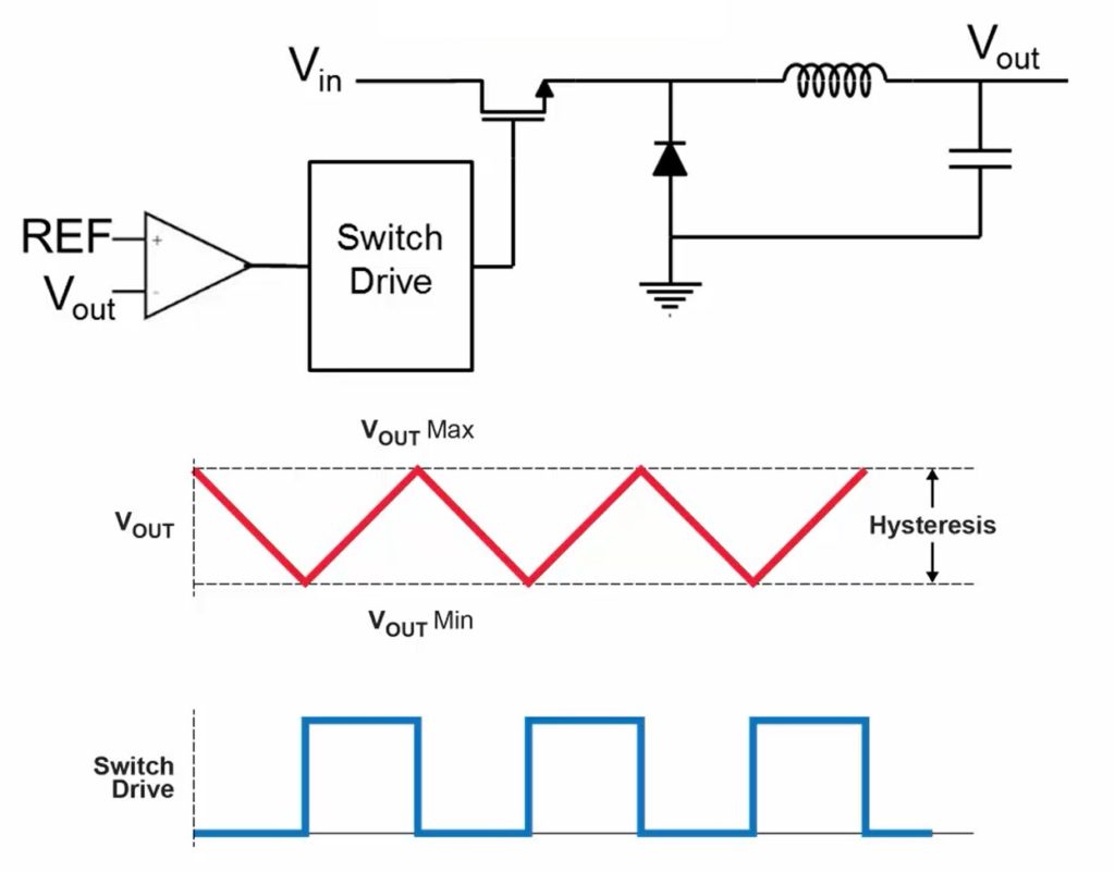
Hysteretic control is asynchronous, responding immediately to voltage variations caused by step load changes. Voltage and current mode controllers use a clock signal and must wait until the next clock cycle before responding to any voltage deviation. The fast transient response of hysteretic control reduces the amount of output capacitance needed but at the expense of variable frequency operation. Voltage-mode or current-mode control should be used in applications that cannot easily accommodate a variable frequency power supply.
Only the output voltage is monitored through a feedback loop in voltage mode control. Voltage-mode control synchronizes the pulse-width-modulation (PWM) control with a clock signal (Figure 4). It requires loop compensation to maintain stability, making it more difficult to implement than hysteretic control. At the beginning of each clock cycle, the control switch is turned on, delivering energy to the output. The compensated error voltage, obtained by combining the output voltage with the reference voltage in an error amp, is compared with the triangular wave from the PWM generator. When the ramp of the PWM signal intersects the compensated error voltage, the controller turns off the control switch which remains off until the next clock pulse.
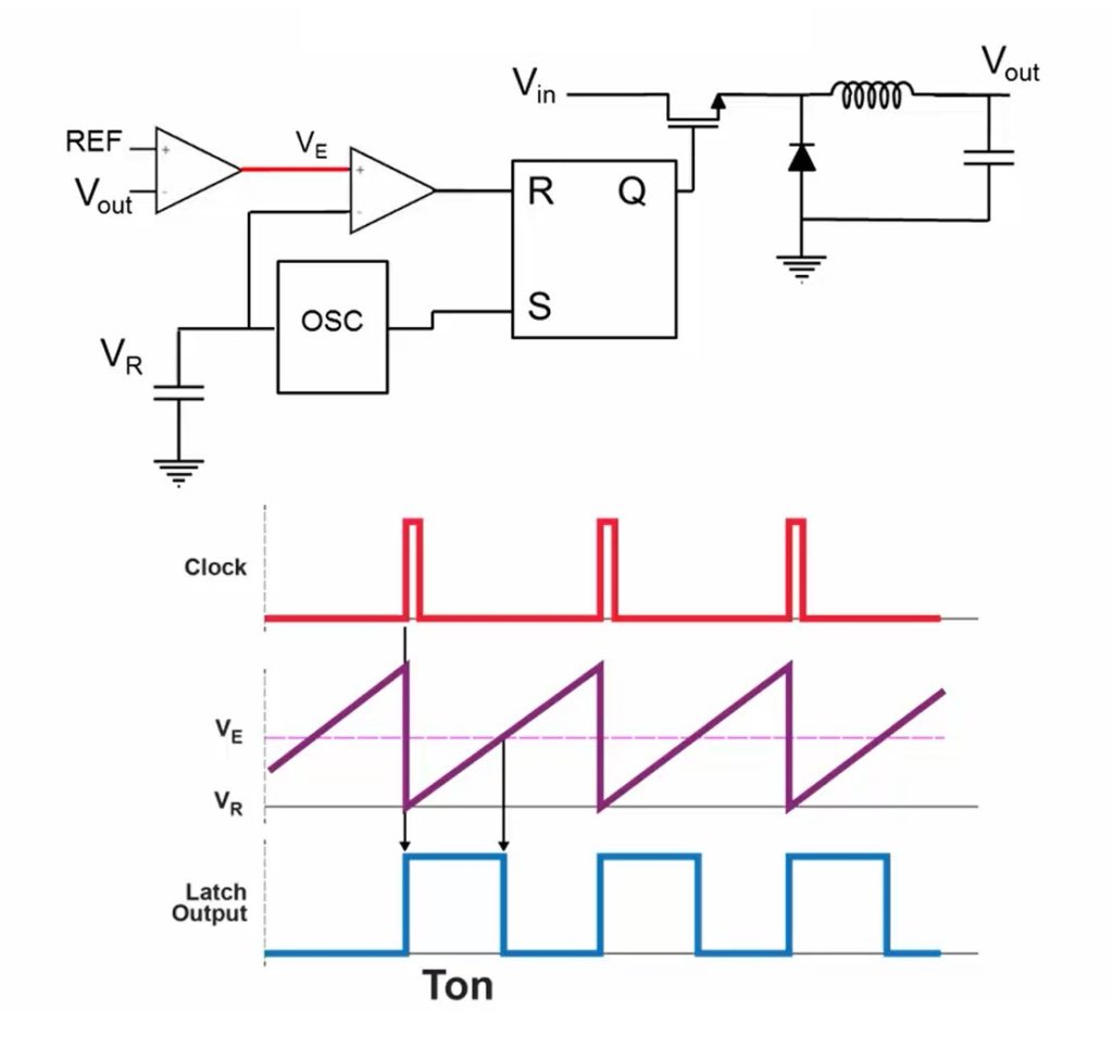
Advantages of voltage-mode control are its relative simplicity based on using a single voltage feedback loop, the ability to control shorter on-times, and good noise immunity. Unfortunately, while the feedback looks simple, compensation is complex, and the design of voltage-mode power supplies can be relatively challenging.
Current-mode control is also synchronized with a clock signal. But it has a different set of design and performance tradeoffs compared with voltage-mode control. At the beginning of each clock cycle, the control switch is turned on, delivering energy to the inductor (Figure 5). Like voltage-mode, an error amplifier compares the output to a reference. Current-mode also monitors the inductor current. The switch is turned off when the sensed current intersects the error amplifier voltage.
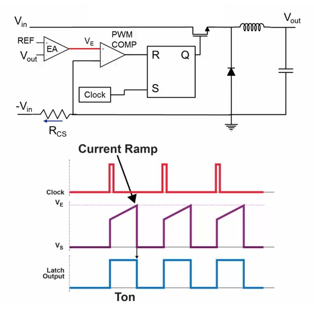
Current-mode control eliminates the inductor from the loop, resulting in a single-pole transfer function related only to the output capacitance and load resistance. One challenge with current-mode control is that noise from the switching transitions can corrupt the current feedback signal resulting in premature turn-off of the PWM cycle. Leading-edge blanking is commonly used to address this concern. Current-mode designs are usually more expensive since they include both voltage and current feedback loops. Subharmonic oscillations that can occur in duty cycles of 50% or higher are limitations of current-mode control. This can be addressed using slope compensation techniques that result in additional design complexity.
Current-mode is a very popular control method due to its fixed-frequency operation, simplified current limiting, parallelability, good transient response, and relative ease of compensation. Each of the three basic power supply control techniques offers different performance tradeoffs and design challenges (Table 2).

Digital is different
Digital proportional-integral-derivative (PID) controllers have been used in (relatively slow) motor control loops for decades. But the adaption of PID control for high-frequency switched-mode power supplies is a relatively recent development. PID control can monitor and control both voltage and current.
In a PID algorithm, each of the three terms has a specific purpose (Figure 6). The error between the target output voltage and the actual output voltage is the proportional term used to provide the major part of the control loop command output. The integral term contains the accumulation of the proportional errors and helps to move the control system to the desired output voltage. Without the integral term, the proportional term’s effect on reaching the desired output voltage diminishes as the error is reduced. The change in the proportional error over time comprises the derivative term. The derivative term is used to moderate transient conditions and provide high-frequency gain for the control loop.
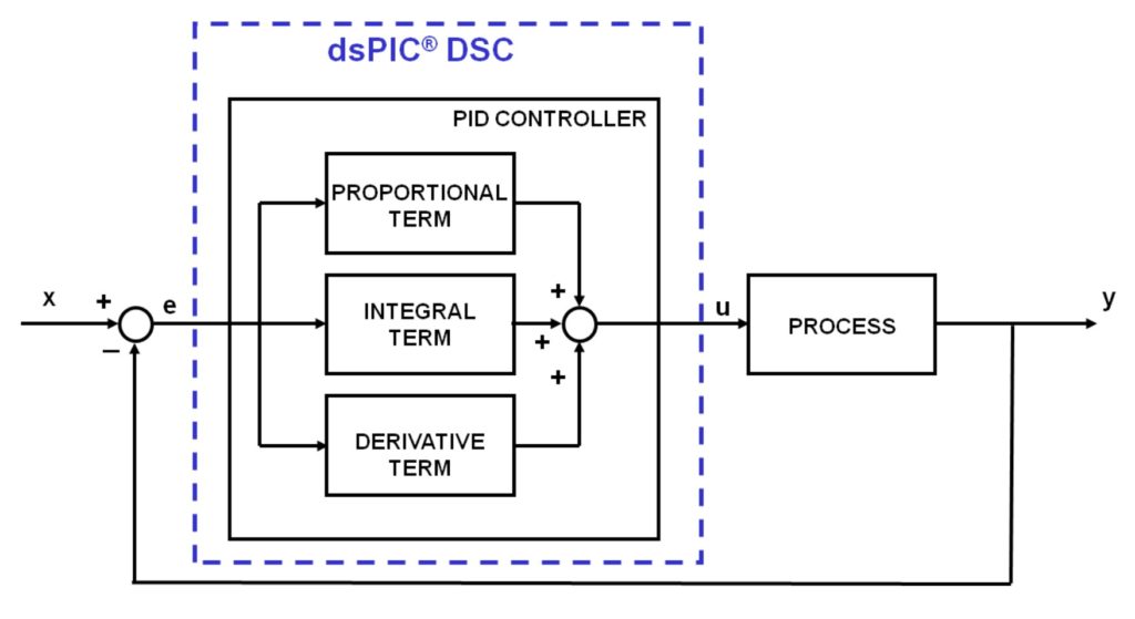
More advanced PID algorithms include “feed-forward” terms. Conventional PID control relies on a measured error in the output voltage to create the command needed to move toward the desired output voltage. Digital signal processors (DSPs) and microprocessors (MCUs) can be used to add more terms to the PID equation. The basic feed-forward term is used to create an “ideal” control loop command based on the input voltage system component values and the desired output voltage. The feed-forward term is added to the basic PID terms to improve stability and overall performance.
In more advanced implementations, anticipated load current changes can be added to the feed-forward equations. Some large digital ICs such as MCUs enter sleep mode to minimize thermal dissipation when they are not active. An MCU preparing to emerge from sleep mode can signal the power supply in anticipation of the need for current, resulting in a faster transient response. Feed-forward terms can anticipate that type of system changes before they are reflected in the power supply’s output voltage. These feed-forward terms are inherently stable and “anticipatory”.
Advanced digital control algorithms can dynamically change the control parameters and adapt to changing operational conditions such as input voltages and load conditions, turning on and off phases in multi-phase architectures, and complex system power management schemes. Digital control also enables the use of complex power conversion topologies, such as resonant and quasi-resonant converters, that are not easily implemented with analog control techniques.
Summary
Power supply control techniques have advanced significantly over time, beginning with basic ferroresonant and linear power supplies, both of which are still widespread. The development of switched-mode control brought higher efficiency to power conversion, beginning with hysteretic control and voltage mode control, before advancing to current mode control, which simplified feedback compensation. Digital control has enabled more advanced power converter control, including feed-forward control and the ability to dynamically change control parameters to adapt to changing operating conditions and system requirements.
References
Control Methods (Voltage Mode, Current Mode, Hysteresis Control), ROHM Semiconductor
Ferroresonant power supply, Sunpower Electronics
Introduction to Power Control Theory, Texas Instruments
Introduction to SMPS Control Techniques, Microchip
PID Basics, Microchip


Leave a Reply