Special features such as fold-back protection and good dynamic response come in handy for the dc-dc conversion stages powering 5G RANs.
Andy Brown, Advanced Energy Industries, Inc.

With its high speeds, low latency, reliability and potential for rapid scalability, 5G is set to change the way we use and share data and to move concepts such as the connected vehicle and the smart city from the drawing board to reality. Based on a proliferation of small cells, 5G radio access networks (RANs) have demanding power requirements in terms of reliability, efficiency, EMI and the ability to operate in often harsh conditions.
According to the research firm ResearchAndMarkets, the market for 5G infrastructure will see a compound annual growth rate (CAGR) of 55% from 2021 to reach $115.4 billion by 2026. Much of that growth will come from the proliferation of small cells that will need to be added for the line-of-sight coverage over short distances that the higher spectrum frequencies used by 5G demand. These cells are being added to light poles, traffic lights, buildings and other tall structures and are being complemented by pico- and femto-cells for enterprise and residential deployments so as to to create dense 5G heterogeneous networks or HetNets.

DC-DC converters are fundamental elements of every small cell and, depending on the specific application, they will work from a variety of potential input power sources. Communication cells mounted on street lamps, for example, may need to operate from ac mains, while those on top of or inside buildings could use ac or -48-V PoE (Power over Ethernet). Many converters will need to operate with a conventional 12-V power supply, while newer applications could use HVAC or HVDC power. Irrespective of the input power source, reliability, thermal management, efficiency, EMI, noise and protection-attributes will all be among the key criteria in selecting power conversion solutions for 5G RAN infrastructures.
Critical to the success of 5G networks is the ability of the communication cell to operate with maximum uptime. 5G base stations and their active antennae must always operate reliably and, in the case of applications such as connected vehicles and smart cities, ensure safety. In many cases redundancy or even self-diagnosis and self-repair is necessary. And if an engineer does need to be called out, it is essential that fixes take place without any break in service.

This need for reliability means that the power supplies for the base station must have Mean Time Between Failures (MTBF) calculated in the millions rather than a few hundred thousand hours, irrespective of the harsh outdoor environment in which they operate. Heat is a key contributor to power supply failures. (The rule of thumb for MTBF is that every 10°C rise in component temperature halves the MTBF.) So designers must concentrate on optimizing thermal management.
Deployed close to (or in) the antennas located on cell towers or roof tops, the RF circuitry of the remote radio head (RRH) provides signals via fiber optic cable to a base band unit (BBU) sitting inside a shelter or cabinet at the base of the tower. The RRH is usually powered by a low-voltage power line (typically 48 and 52 Vdc) at the top of the tower next to the antenna. Some newer applications use ac or higher voltage dc to lessen the cable size and hence reduce the weight and cost of the cables the cell tower must support. Unfortunately, RRHs are notoriously inefficient and typically range between 35 to 45% power-in-to-power-out, with most of that residing in the transmitter amplifier. This inefficiency contributes to overall expense, and operators are constantly seeking to improve it.
Fortunately, power amplifier (PA) efficiency has improved significantly in recent years. This is due in large part to more sophisticated linearization techniques and newer design and component technology that enables higher output power capabilities. In terms of power requirements, where the amplifier is 300 to 400 W, an LDMOS (RF laterally diffused MOS) power amplifier may need that power at 28 Vdc whereas an amplifier built around gallium nitride (GaN), could need approximately 50 Vdc. In addition, there is usually a 12-V rail that may be required to provide 60 to 100 W to power the data processing functions.
The problem is that next-generation “massive MIMO” active antenna unit (AAU) radios need a large number of lower-power amplifiers for each AAU radio. Linearizing each of these small amplifiers is costly and marginally effective because the additional circuitry itself consumes much of the power that it is designed to save.
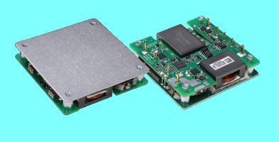
Use of the latest high-efficiency dc-dc converters for the PA power supply can boost overall system efficiency and reduce operation costs. The Artesyn ADH700 series of half-brick isolated dc-dc converters, for example, offers an ultra-high conversion efficiency exceeding 95% at half load. And of course, the more efficient the power conversion, the lower the dissipated heat and the easier the thermal management.
Many of these newer converters offer a wide range of output voltage adjustment (from 50 to 118% for the ADH700) which improves PA efficiency and reduces the need for cooling. In this case designers can optimize performance and efficiency by configuring the PA voltage to follow changes in the PA envelope by using the voltage output trim pin on the power supply.
When implementing a PA power supply design it is important to:
Ensure there are safeguards to the protect the overall system.
Ensure that EMI and regulatory requirements are met
Match the dynamic load response of the power converter to what the system requires. We’ll discuss each of these points in turn.
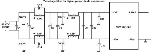
 Safeguards: An input circuit at the front end of the dc-dc converter must include a fuse and Metal Oxide Varistor (MOV) for surge suppression, as well as a Negative Temperature Coefficient (NTC) inrush limiting power thermistor for powering and protecting the RF architecture. For higher power dc-dc conversion applications a two-stage filter will typically be deployed.
EMI and regulations: A good input filter and layout design will minimize the EMI signature. Fast-switching currents in associated circuitry can generate magnetic fields and fast-changing voltages create electric fields that may result in undesired coupling. Electromagnetic coupling can be minimized by the use of solid grounds and shielded cases.
Use of multiple vias for bypass capacitors can reduce resistance and inductance. Also, designers should ensure that ground-voltage potential remains stable and never floats.
Traces that carry high-frequency signals generate a time-varying electromagnetic wave that can propagate and cause interference. Two traces at a 90° angle will cause the least interference between the two signals they carry. A good case ground also helps prevent outside signals from entering the system as well as providing shielding. The ground loop for the RF should also be kept separate from the ground loop of the noisier digital components.
Dynamic load respons5e: Power converter load response demands selection of the appropriate output capacitors that match with the power converter control characteristics to meet the system demands. Dynamic load changes can quickly discharge output capacitance, causing the output voltage to drop out of its static regulation specification.
Even if the load step draws current that is within the rated current of the power supply, there may be some “droop” in the output voltage. A voltage feedback circuit senses the droop, which in turn causes the supply to boost the output voltage to bring the unit back within static voltage regulation specification. This correction doesn’t happen instantly. Typically a 10% to 90% voltage recovery time is specified, along with a percentage of maximum rated voltage overshoot allowable.

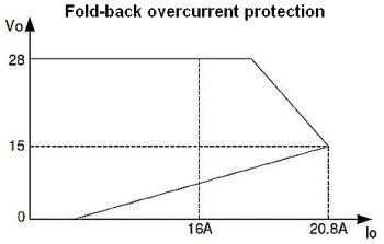
A further consideration when it comes to protection is a characteristic known as fold-back mode overcurrent protection. With normal (high side) current limiting the current is limited to a fixed value as the load resistance approaches zero and the supply voltage begins to drop. With foldback protection, the current limit also drops fairly linearly as the output voltage drops. This provides more protection because extreme short circuits won’t cause a large current draw.
Fold-back mode protection is especially useful when powering a ‘peaky’ RF power amplifier, which has the potential to affect the power supply. In general, the designer does not want the dc-dc power supply to see a fast peak. The power supply could interpret this peak as a fault, go into a shut-down mode, and switch off the output voltage while it attempts to reset and restart. Fold-back mode prevents this scenario by allowing for some level of voltage output without automatically turning off the output voltage completely.
Furthermore, to manage the fast-spiking load nature of the PA, some applications may have a large output capacitance on the order of tens of thousands of microfarads. Starting up a power supply in such a load is usually difficult because these capacitors will initially look like a short circuit. Use of a dc-dc converter with a fold-back characteristic eliminates the problem.
Size is the final consideration when selecting dc-dc converters for 5G RAN applications. While they are not as space-limited as many consumer applications, converters for 5G cells must still be as small and as light as possible. Manufacturers try to minimize the overall cell size so the demand for low-profile, small-footprint supplies will grow.


Leave a Reply