Overlapping protocols and competing standards have created a confusing landscape for USB chargers. Here are the important differences and similarities of most interest to designers.
Masashi Nogawa, Staff Systems Engineer Qorvo
The first standard for charging via USB connections allowed power delivery at a 7.5-W maximum. Recently the USB standard jumped up to support 100 W. The fast charging this change makes possible is attractive but can be confusing for designers to navigate. Several charging protocols have been developed to handle the new capabilities, and programmable power supplies (PPS) now help mitigate the heating challenges.
To understand the advantages of this generation’s fast charging technologies, it is helpful to review the battery charger fundamentals of the lithium-ion packs powering mobile devices. On a charger, greater currents and higher voltages charge batteries faster, but too much power leads to overheating, and we all know what happens when a phone battery gets too hot.
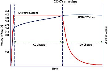 To prevent overheating, the charger circuit uses a charge controller IC to regulate the flow of battery current using a constant-current to constant-voltage (or CC-CV) charting algorithm. This technique is the key to battery charging technologies.
CC-CV charging happens in two phases. In the constant-current phase battery voltage is much lower than its target. The fast charger pushes high currents into the battery, speeding the charging process. The constant-voltage phase begins once the battery has received most of its charge. At that point, the IC will reduce the current to prevent overcharging.
The major sources of overheating are the lithium-ion battery packs and the transistors of CC-CV charger ICs. Not much can be done about the battery pack heat–after all, the battery must charge. Instead, designers focus on dissipating the heat from the charger ICs.
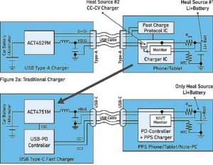
Consider a traditional battery charging system using the standard Type-A USB cable. This setup must mitigate heat from both the charger and the battery. The USB-A delivers 5 V (and 9 or 12 V in some propriety schemes) to the device using the VBUS wire, but a lithium-ion battery can take a maximum 4.2 V. Thus the CC-CV controller in the charger IC block must reduce the voltage input to 4.2 V for charging. A power loss always accompanies the conversion of one dc voltage to another, generating unwanted heat.
Thanks to technological innovations, we can remove the CC-CV controller from mobile devices. Thus the battery pack is now the principal heat source. The basic structure of a fast charger that employs the latest USB-C cable and PPS protocol uses a power delivery controller, or PD-controller. The PD-controller coordinates with the PPS charger to pass voltage from the USB-C (VBUS) directly to the battery without dc-to-dc conversion. This approach dramatically reduces the power losses that cause heat.
The PD-controller + PPS charger block also monitors battery charging voltage, current, and temperature to optimize CC-CV charging. It determines target values for voltage and current, then requests the right levels from the charger at the other end of the USB-C cable. This approach gives designers precise control over output current and voltage. For example, Qorvo PPS power ICs allow for voltages from 3.3 to 21 V in 20-mV steps and currents from 1 A to a charger’s maximum in 50-mA steps.
In another example of a fast charger implementation with PPS, the VBUS of the USB-C cable directly goes to the battery pack(s). Higher charging current flows over the entire charging path, causing higher conduction power loss (= Icharge2× Rpath). With recent dc-to-dc voltage conversion technologies, high-efficiency switching takes place at a specific input and output voltage ratio. For example, a ratio of Voutput = Vinput × ½ can be efficient. When VBUS voltage doubles, both the charging current and conduction losses are halved.
Fast charging protocols
OEMs like Apple, Samsung and Xiaomi have been increasingly adopting fast charging features, while new technologies like USB Power Delivery and Qualcomm Quick Charge are competing for market share. And power engineers expect many USB chargers will support the Power Delivery 3.0 Programmable Power Supply (USB PD 3.0 PPS) standard. It is worth taking a closer look at recent fast charging device applications and the competing standards.
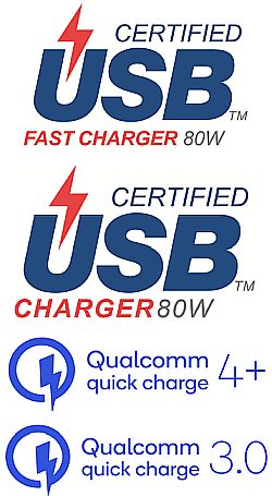
There is a special USB Implementers Forum (USB-IF) Fast Charger logo to indicate a charger is certified for 80 W USB 3.0 PPS. There is also a “non-fast” charger logo. The only difference is the lower red line of the logos read “FAST CHARGER” or just “CHARGER” respectively.
Several phones employ this USB Fast Charger technology. For example, Samsung calls it Super Fast Charging or Super Fast Charging 2.0 on its USB PD 3.0 PPS-supported Note 10+ and Galaxy S20 5G devices. Xiaomi phones that include Mi 8 and Mi 9 support QC4+.
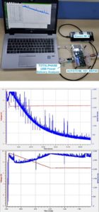
Now consider how actual charging voltage and charging current change over time on a modern smartphone. Suppose an Xiaomi Mi 9 phone is charged by a QC4+ charger, ACT4751M_101_REF05. Throughout the entire charging sequence, this Xiaomi phone maintains its maximum charging current exactly at 2.9 A though the charger supports 4 A and the USB-C cable can handle 5 A. A PD controller clips charging current peaks at 2.9 A in this Xiaomi phone.
At the beginning of this charge sequence, the phone demands around 9.6 V of VBUS voltage and, eventually, the phone demands 7.0 V by reducing VBUS voltage step-by-step over about 2.5 minutes. Once VBUS reaches 7.0 V, a charger IC inside the phone maintains operation at this voltage. It appears this 7.0-V supply point is an optimal operating point for the Mi 9 charger IC. Thus the Xiaomi Mi 9 uses the USB PD 3.0 PPS function and/or QC4+ function to program VBUS at 7.0 V, different than the standard 5/9/15/20-V options.
Type-A cable
During the era of Type-A port charging, many vendors adopted features (some incompatible with today’s standards) to support higher power and faster charging. These Type-A port technologies remain in USB-C protocols today for the sake of backward compatibility. The original Type-A port specification supported only 2.5 W (5 V/0.5 A). These days, it is difficult to find a charger supplying so little power. The original 2.5-W USB charger spec was upgraded to 7.5 W by the specification of Battery Charge rev. 1 (BC1.2). This remains the highest official power level USB-IF recognizes for Type A ports. All other higher power Type-A port protocols are not compatible with USB-IF standards.
There are many privately defined charging methods available that are outside of official USB specifications. Examples include Qualcomm’s Quick Charge 2.0 and Quick Charge 3.0, along with protocols for phones from major OEMs like Apple, Samsung, and others.
At a Type-A port, there are only four pins available–one pair of VBUS and GND (power rails) and D+/D- (data lines). To charge a device through a Type-A port, we need VBUS and GND constantly, so all Type-A port base charging methods use D+/D- lines for logic handshaking to establish charging control.
Protocols including BC1.2, Qualcomm QC2 and QC3, and those used by Apple and Samsung all employ the D+/D- lines in different ways for handshaking. The details of these protocols are beyond the scope of this article, but it is important to note we use D+/D- lines for charging controls because USB-C ports include D+/D- lines for backward compatibility.
It is worth visiting Quick Charge 3.0. Though QC3 is not a USB PD 3.0 base, it achieves the same goal of PD 3.0 PPS or QC4+/QC4 through Type-A ports. QC3 supports programmable voltages in 200 mV steps. The intention of this fine-step voltage control is the same as for PPS: to reduce power loss and heat from a battery charger IC inside a phone or tablet.
Unlike the Type-A port specification, the power delivery 3.0 (PD 3.0) specification of USB-C supports up to 100 W of power delivery from the onset, so almost all USB-C chargers follow this spec. One source of confusion is that the physical specifications for the USB-C port differ from PD 3.0 specifications. This has important implications: Not all USB-C ports support PD 3.0. Some uses of physical USB-C ports replace old Type-A and Type-B connections where only D+/D- pins are used. Thus a physical USB-C port does not guarantee the existence of PD 3.0 fast charging capabilities.
Many charger products with USB-C ports are normal PD chargers, not USB Fast Chargers. Based on the PD 3.0 specifications, standard VBUS voltage options are 5, 9, 15 and 20 V. Because these normal PD chargers produce a fixed (non-programmable) VBUS voltage, they are the same as traditional Type-A port chargers in terms of battery charging efficiency.

One easy way to identify USB Fast Chargers with PD 3.0 PPS capabilities is the USB logo: The red bottom line will say “FAST CHARGER.” To distinguish their products from normal non-PPS PD chargers, most of vendors get their faster chargers certified by the USB-IF.
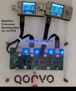
A USB protocol tester can easily discern whether or not a USB-C port supports PPS. In addition to the basic fixed 5, 9, 15, and 20-V options, a USB Fast Charger offers a programmable output option.
A charger with Quick Charge 4 can be compatible with USB Fast Charger. It is also possible to get one product certified for both USB Fast Charger and Quick Charge 4. A certification test of QC4 chargers requires tighter regulation of output voltage and current compared with that for USB Fast Chargers. Although it is difficult to tell the difference between a USB Fast Charger and QC4 charger without logos or product labels, there are some key differences. For example, QC4 chargers can report the charger’s internal temperature by its specification. This feature can potentially let a phone supporting QC4 charge its battery faster than USB Fast Chargers.
The difference between QC4 and QC4+ is the Quick Charge 2.0/Quick Charge 3.0 backward compatibility. QC4+ supports QC2 and QC3 through D+/D- lines. Through use of a USB-C-to-USB-2.0 Micro-B cable, phones without a USB-C port can still get a quick charge from a QC4+ capable USB-C charging port. Because QC2 and QC3 are incompatible, a QC4+ capable charger cannot get certified as a USB Fast Charger.
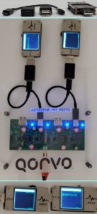
To make matters more complicated, there are some Asian phones whose connectors have the physical shape of USB-C, but their communication/handshaking protocols do not follow the USB PD 3.0 specification.
Thus it is easy to see why power electronics engineers have a difficult time explaining new fast charging technologies consumers. The indistinct marketing and branding efforts for these new technologies has only added complexity.



No mention is made of the reduction in battery capacity caused by fat charging. In fact, the effect is often ignored and denied. The damage done is seldom obvious until many cycles later.and so the blame is seldom placed correctly.