PMICs today do a lot more than just regulate voltages. Here’s a look at high-end functions these devices provide.
Narasimhan Trichy • Qorvo
Superior power management and high efficiency have become essential as electronics have become increasingly smaller and more streamlined. The reduction of power dissipation and consequent heat and thermal issues is critical to improving both battery life and the product reliability. Key components are the high-efficiency regulators that handle a wide range of power requirements and remain efficient across a wide range of load currents. Likewise, high efficiency during heavy loads is critical for mitigating heat and power dissipation.
A Power Management Integrated Circuit (PMIC) is an efficient and integrated way to distribute power in a complex system with multiple power rails or regulators. With configurable and adjustable functions and parameters, PMICs can be preprogrammed and optimized on the fly, using an I2C interface. Qorvo PMICs are firmware-compatible for easy control and suitable for dynamic power management in electronics requiring several low-power states.
Selecting a suitable PMIC
Step 1: Identify the number of power rails required. A typical system may contain a multitude of subcomponents such as a main system controller or processor, sensors, a screen or graphical interface, and so on. Each of these may need to be enabled or disabled independently or can be combined to be powered from a single 
an integrated regulator on a Qorvo PMIC. Click image to enlarge.
Step 2: Identify the required capacity of each power rail. Typically, every regulator serves as a power supply to one or more system components. The maximum load current the regulator must support is the load requirement or necessary capacity. Thus each regulator should have enough load capacity to match or exceed the desired load. The maximum load current drawn by each of the components to which the regulator supplies power must be added to get the total load current requirement. In a nutshell, the regulator must provide a voltage range and output current that each rail needs..
Step 3: Consider the input power source. A USB or single-battery system would use an input power source of 5 V or lower. A standard lithium-Ion/lithium-polymer battery has a useful voltage range of ~2.7 to ~4.4 V. Applications such as a laptop or desktop computer, or enterprise storage or computing, could use voltages up to 18 V. The input voltage of PMICs can differ, and the voltage range of the input power source must be lower than the maximum voltage rating of the PMIC itself. A higher-voltage PMIC may be used in a lower-voltage system but not vice versa.
System functions could include system reset signals, power-good signal generation, power sequencing during power- up, power-off sequence when turning off components, low-power states when power saving is enabled, battery/ input-voltage monitoring for under- and over-voltage detection, fault detection in regulators, fault reporting and diagnostics, interrupt functions, push-button interface, GPIO wake and trigger functions, signal voltage level shifting, controlling external regulators, monitoring external regulator outputs for power-good, and many others.
A suitable PMIC with adequate GPIOs and system functions can minimize the need for external components and minimize the overall cost of the system. Integration of most system functions into the PMIC also reduces the system footprint. These system functions are critical but are easily overlooked when comparing costs and simplicity of PMICs to discrete solutions.
Firmware compatibility is an important aspect for modern electronics. Many applications today are battery powered. One way to lengthen battery life is by tweaking power sequences, adjusting low-power-mode behavior, lowering voltage, and adjusting current supplies dynamically when they are lightly used. Firmware upgrades can implement such tweaks well after the products are deployed in the field.
Over-the-air upgrades are now ubiquitous and demand a level of sophistication in power management that Qorvo PMICs offer. The use of multiple time programmable (MTP) and non-volatile technology lets Qorvo PMICs be programmed more than once, and programming can take place in the field. (MTP is a kind of non-volatile memory manufactured via a relatively simple, economical process.) This technology helps create field-programmable products, but the goal is to avoid any firmware intervention or programming. It is desirable to configure PMICs so there is little need for firmware support and to ensure they function autonomously, supporting firmware control only when necessary.

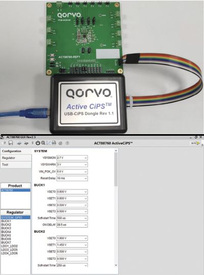
Designers traditionally like the control that discrete components provide. The designer can choose different components and a means to adjust external resistors to set voltages, control current limits or change on/off times for each power supply. Qorvo PMICs offer the same controls but without soldering or replacing components. Modifications are via the press of a button using the Qorvo-supplied software GUI on a USB dongle that interfaces the PMIC to the software GUI.
As an example, the output voltage of most regulators on the ACT88760 can be adjusted in 5-mV steps from 0.5 to 1.13 V or adjusted in 20-mV steps to reach up to 3.6 V. Current limits can be adjusted to match with appropriate inductor sizes. A lowering of the current limit can reduce BOM costs by allowing use of inductors that are smaller and which have lower current ratings. Likewise, higher current can be configured when necessary. Such configurability helps avoid last-minute board and BOM changes. It also helps avoid last-minute component changes that can retrigger a certification process.
A final point to note is that MTP NVM can let the same PMIC serve in multiple platforms. This lets inventory be reallocated from one program to another if necessary.
Inside a PMIC
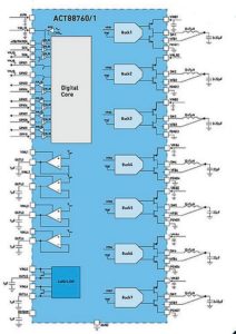
The ACT88760 is a highly integrated PMIC with seven buck regulators (step-down, switching regulators), six LDOs (low drop out regulators), up to 10 GPIOs, and many built-in system monitors and functions. Of the six LDOs, two can be configured as load switches with a low insertion resistance of 25 mΩ. Three of the buck regulators can support dc output loads up to 4 A; two regulators can support up to 3 A and two others support 2 A of load current. Two of the 4-A regulators (Buck1 and Buck2) can operate as a single regulator in two-phase configuration to double the amount of supported load current – up to 8 A.
Likewise, Buck3 and Buck4 can work in parallel to double the output current from 3 to 6 A. Buck7 supports 4 A of current, Buck5 and Buck6 support 2 A each. LDO1 and LDO2 support current output up to 800 mA and can accept input voltage as low as 1.2 V. LDOs 3-6 are rated for a maximum output current up to 400 mA . In the load-switch mode, the output is not regulated, and the input is merely passed on to the output to create a power island with an on/off function.

A description of GPIO functions helps explain the advantages of configurability. The ACT88760 has up to 10 configurable GPIOs. The On/Off control of the PMIC can be selected from three different functions and modes of operation – a push button function, a PWREN (Power Enable) configuration or a PWRON (Power On) configuration. The push-button functions facilitate features used in consumer devices such as cameras, phones, video devices, point-of-sale portals, smart home pods, etc. A single push button can turn-on the device, power-off the device or even initiate a hard reset via a press-and-hold.
The PWREN function uses a different power control state machine more suited to SSD drives and other uses where a single pin can control on/off functions and the initiation of low-power states such as DPSLP (Deep Sleep) or SLEEP. The last mode of operation is the PWRON (Power On) function, in which the operating state machine follows the PWRON input pin as a simple enable signal that can turn on or turn off the PMIC regulators.
Additionally, other GPIOs can be configured as input/output pins in an open-drain configuration or as outputs in CMOS or push-pull configurations. Most GPIOs also include configurable pull-up and pull-down resistors, eliminating the need for external resistors. This feature also provides options for connecting the pull-up resistor to different voltages, such as 1.8 V (I/O voltage) or 5 V (the system voltage, which can also be the same as battery voltage).
GPIOs can perform input functions such as generating an interrupt when the input-signal-status changes. The input signals from GPIOs can turn on regulators, trigger low-power states such as SLEEP, change regulator output voltages for dynamic voltage scaling, accept power-good signals from external regulators, or even trigger power sequences. GPIOs can also generate outputs such as a system RESET, power-good and fault-status indicators for the PMIC or individual regulators, and low-power and status indicators. They can as well control external regulators and sequence their on/ off times, provide interrupt requests, drive LEDs (current sink), and many other such functions. In a nutshell, GPIOs can incorporate many system-level functions and may eliminate the need for house-keeping microcontrollers.


Leave a Reply